Isolated planar mesogyroscope

a planar mesogyroscope and mesoscale disc resonator technology, applied in the field of gyroscopes, can solve the problems of sensing errors and drift, large and heavy, and the mechanism of older conventional mechanical gyroscopes was very heavy, so as to reduce the possibility of friction or anchor loss variability, short resonance decay time, and high thermoelastic damping

Active Publication Date: 2005-08-11
CALIFORNIA INST OF TECH +1
View PDF35 Cites 52 Cited by
  • Summary
  • Abstract
  • Description
  • Claims
  • Application Information

AI Technical Summary

Benefits of technology

[0064] A uniform radial spacing between slots 116, 122 can be employed, but other spacing may also be used, provided two isolated, degenerate radial modes suitable for Coriolis sensing are maintained. In addition, in further embodiments, some or all of the segments 104A-104E can be further slotted such that a single beam segment is further divided into a composite segment including multiple parallel segments. Selective use of such composite segments can be used to adjust the frequency of the resonator 100 Generally, adding slots 116, 122 to form composite circumferential segments lowers the resonator 100 frequency. The effect of machining errors is also mitigated with multiple slots. Although such composite segments are preferably applied to the circumferential segments 104A-104E, the technique can also be applied to the radial segments 102A-102E or other designs with other segments in other resonator patterns.
[0065] Employing the in-plane design described, embodiments of the present invention obtain many advantages over other out-of-plane gyroscopes. For example, the central support bond carries no vibratory loads, eliminating any friction possibility or anchor loss variability. In

Problems solved by technology

Older conventional mechanical gyroscopes were very heavy mechanisms by current standards, employing relatively large spinning masses.
Currently, this is often performed with expensive conventional spinning mass gyros (e.g., a Kearfott inertial reference unit) or conventionally-machined vibratory gyroscopes (e.g., a Northrup Grumman hemispherical resonator gyroscope inertial reference unit).
However, both of these are very expensive, large and heavy.
This transfer or coupling admits external disturbances and energy loss indistinguishable from inertial rate input and hence leads to sensing errors and drift.
Other planar tuning fork gyroscopes may achieve a degree of isolation of the vibration from the baseplate; however, these gyroscopes lack the vibrational symmetry desirable for tuned operation.
However, these designs are not suitable for or have significant limitations with thin planar microfabrication.
However, its high aspect ratio and three-dimensional (3D) curved geometry is unsuitable for inexpensive thin planar microfabrication.
The thin ring gyroscope (e.g., U.S. Pat. No. 6,282,958, which is incorporated by reference herein), while suitable for thin planar microfabrication, lacks electrostatic sensors and actuators that take advantage of the extensive planar area of the device.
Furthermore, the symmetry of shell-mode gyroscopes is inherently limited by the average mechanical precision of only the two machining cuts used to define the inner and outer surface.
Moreover, the electrical baseplate or case for this gyroscope is not of the same material as the resonator proof mass so that the alignment of the pickoffs and forcers relative to the resonator proof mass change with temperature, resulting in gyroscope drift.
This drift issue is further compounded when the electrical base or case of the gyroscope chip is mounted flat to a platform of dissimilar material, as typical with electronic chip components.
However, such increased isolation comes at the expense of proportionately heavier seismic mass and/or lower support frequency.
Both effects are undesirable for compact tactical inertial measurement unit (IM

Method used


Image

  • Isolated planar mesogyroscope
  • Isolated planar mesogyroscope
  • Isolated planar mesogyroscope

Examples


Embodiment Construction

[0047] In the following description of the preferred embodiment, reference is made to the accompanying drawings which form a part hereof, and in which is shown by way of illustration a specific embodiment in which the invention may be practiced. It is to be understood that other embodiments may be utilized and structural changes may be made without departing from the scope of the present invention.

1.0 Overview

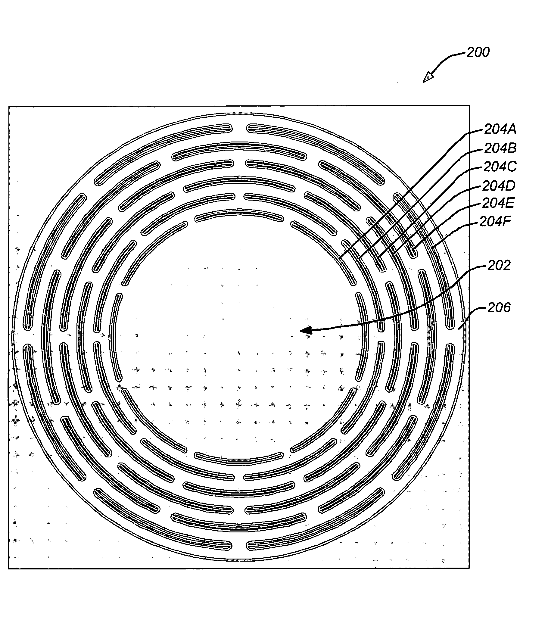
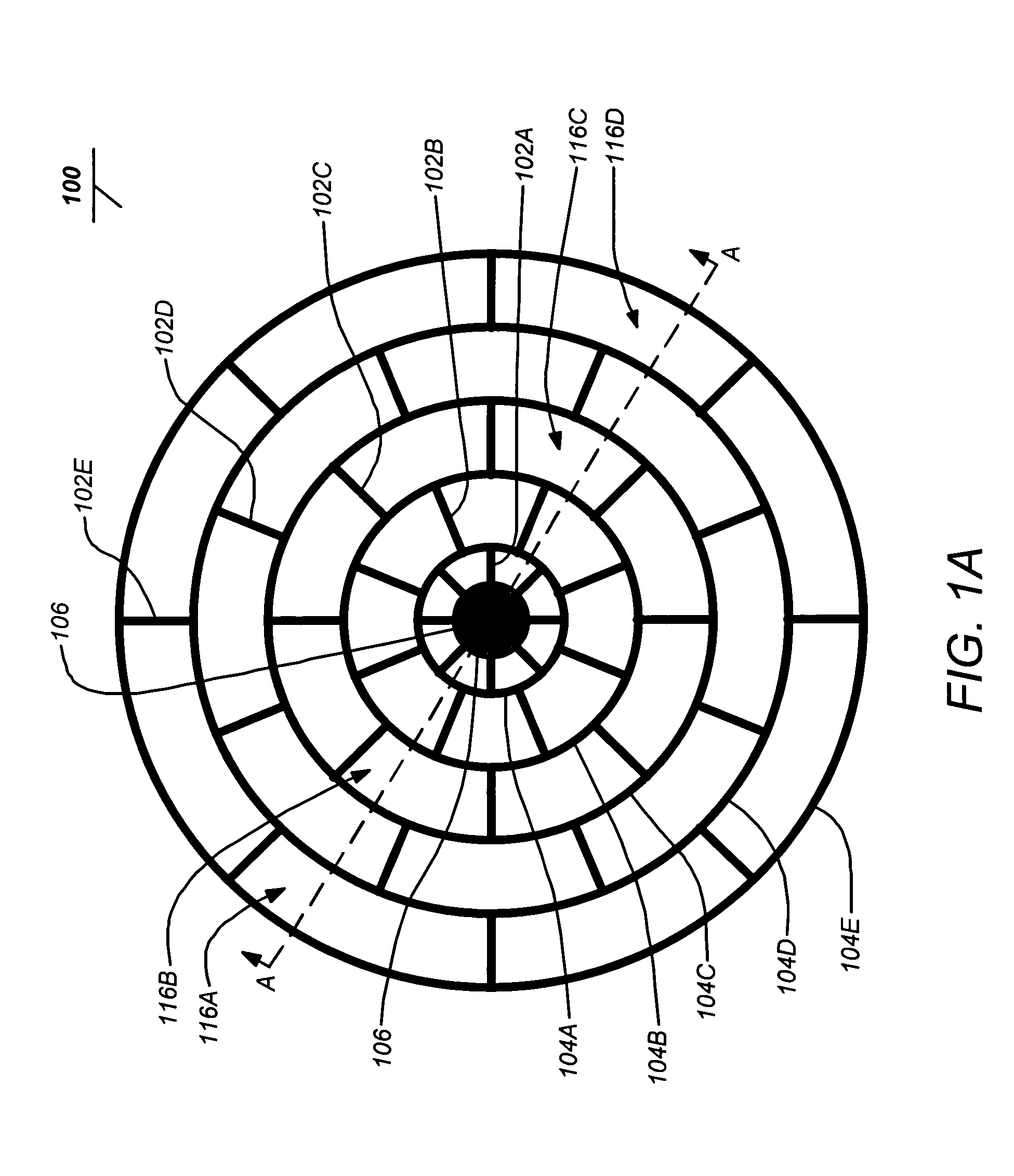
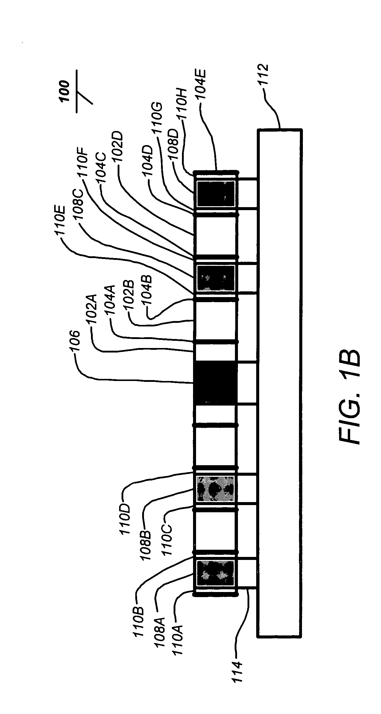
[0048] The present invention describes a micromachined, Coriolis-sensing, mesogyroscope with thick mesoscale, adiabatically vibrating elements and an electrically conductive resonator for electrostatic sensing, actuation and trimming. The two-dimensional (2D) micromachined wafer fabrication of this mesogyroscope results in lower cost and higher precision than one-at-a-time, conventional, 3D machined, Coriolis-sensing, mesoscale gyroscopes, and has higher mechanical precision and performance than other micromachined gyroscopes with thin microscale, isothermally vibrating elem...


PUM

PropertyMeasurementUnit
Frequencyaaaaaaaaaa
Frequencyaaaaaaaaaa
Frequencyaaaaaaaaaa

Abstract

An inertial sensor includes a mesoscaled disc resonator comprised of micro-machined substantially thermally non-conductive wafer with low coefficient of thermal expansion for sensing substantially in-plane vibration, a rigid support coupled to the resonator at a central mounting point of the resonator, at least one excitation electrode within an interior of the resonator to excite internal in-plane vibration of the resonator, and at least one sensing electrode within the interior of the resonator for sensing the internal in-plane vibration of the resonator. The inertial sensor is fabricated by etching a baseplate, bonding the substantially thermally non-conductive wafer to the etched baseplate, through-etching the wafer using deep reactive ion etching to form the resonator, depositing a thin conductive film on the through-etched wafer. The substantially thermally non-conductive wafer may comprise a silicon dioxide glass wafer, which is a silica glass wafer or a borosilicate glass wafer, or a silicon-germanium wafer.

Description

CROSS-REFERENCE TO RELATED APPLICATIONS [0001] This application claims the benefit under 35 U.S.C. §119(e) of the following U.S. provisional patent application: [0002] U.S. Provisional Patent Application Ser. No. 60 / 561,323, filed Apr. 12, 2004, by A. Dorian Challoner and Kirill V. Shcheglov, entitled “MESOGYROSCOPE,” docket number CIT-4078, [0003] which application is incorporated by reference herein. [0004] This application is a continuation-in-part under 35 U.S.C. §120 of the following co-pending patent applications: [0005] U.S. Utility patent application Ser. No. 10 / 639,134, filed Aug. 12, 2003, by Kirill V. Shcheglov and A. Dorian Challoner, entitled “CYLINDER GYROSCOPE WITH INTEGRAL SENSING AND ACTUATION,”, docket number PD-02-0093A (147.105-US-U1), which application claims the benefit under 35 U.S.C. § 119(e) of U.S. Provisional Patent Application Ser. No. 60 / 402,681, filed Aug. 12, 2002, by Kirill V. Shcheglov and A. Dorian Challoner, entitled “CYLINDER GYROSCOPE WITH INTEGR...

Claims


Application Information

Patent Timeline
IPC IPC(8): G01C19/56
CPCG01C19/5684Y10T29/49002Y10T29/49007Y10T29/435Y10T29/4902
Inventor CHALLONER, DORIAN A.SHCHEGLOV, KIRILL V.
Owner CALIFORNIA INST OF TECH
Why Eureka
Try Eureka