
Methods and apparatus for enhancing venturi suction in eductor mixers

a technology of eductor mixer and suction tube, which is applied in the direction of filtration separation, wellbore/well accessories, separation process, etc., can solve the problems of increasing the cost of doing business, clogging up the drain line from the kitchen to the grease trap, and animal fat rendered during the cooking process can congeal, so as to increase the amount of secondary fluid drawn, increase the length of venturi suction, and increase the effect of efficiency

Inactive Publication Date: 2005-08-11
HYDROTREAT
View PDF50 Cites 48 Cited by
  • Summary
  • Abstract
  • Description
  • Claims
  • Application Information

AI Technical Summary

Benefits of technology

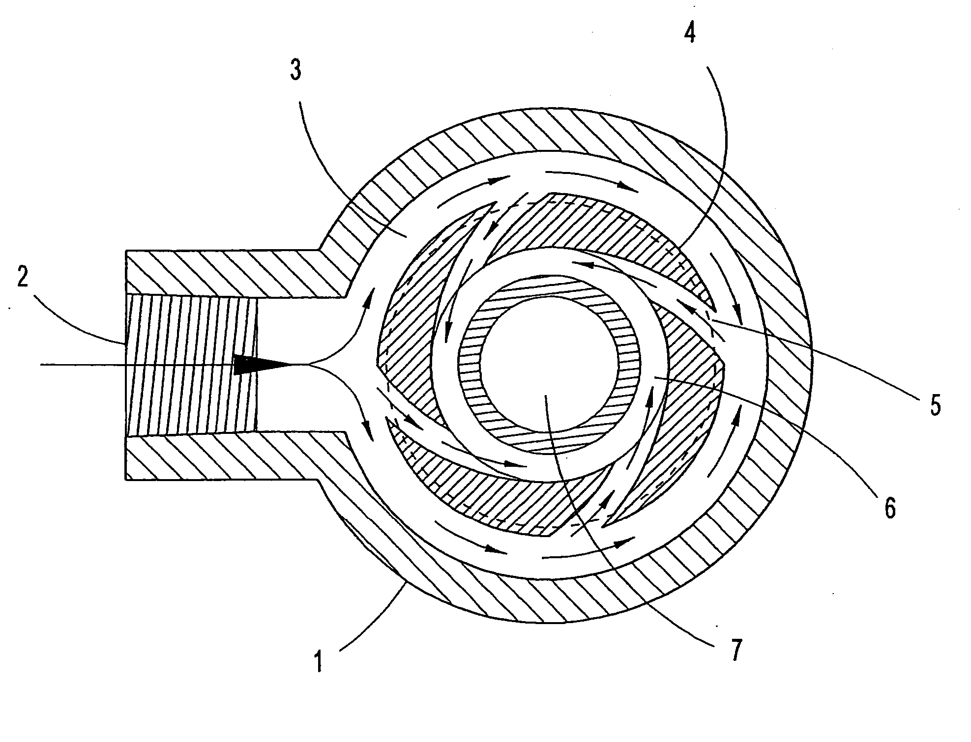
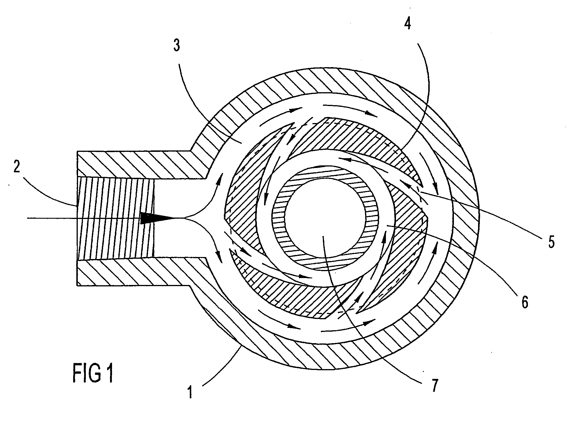
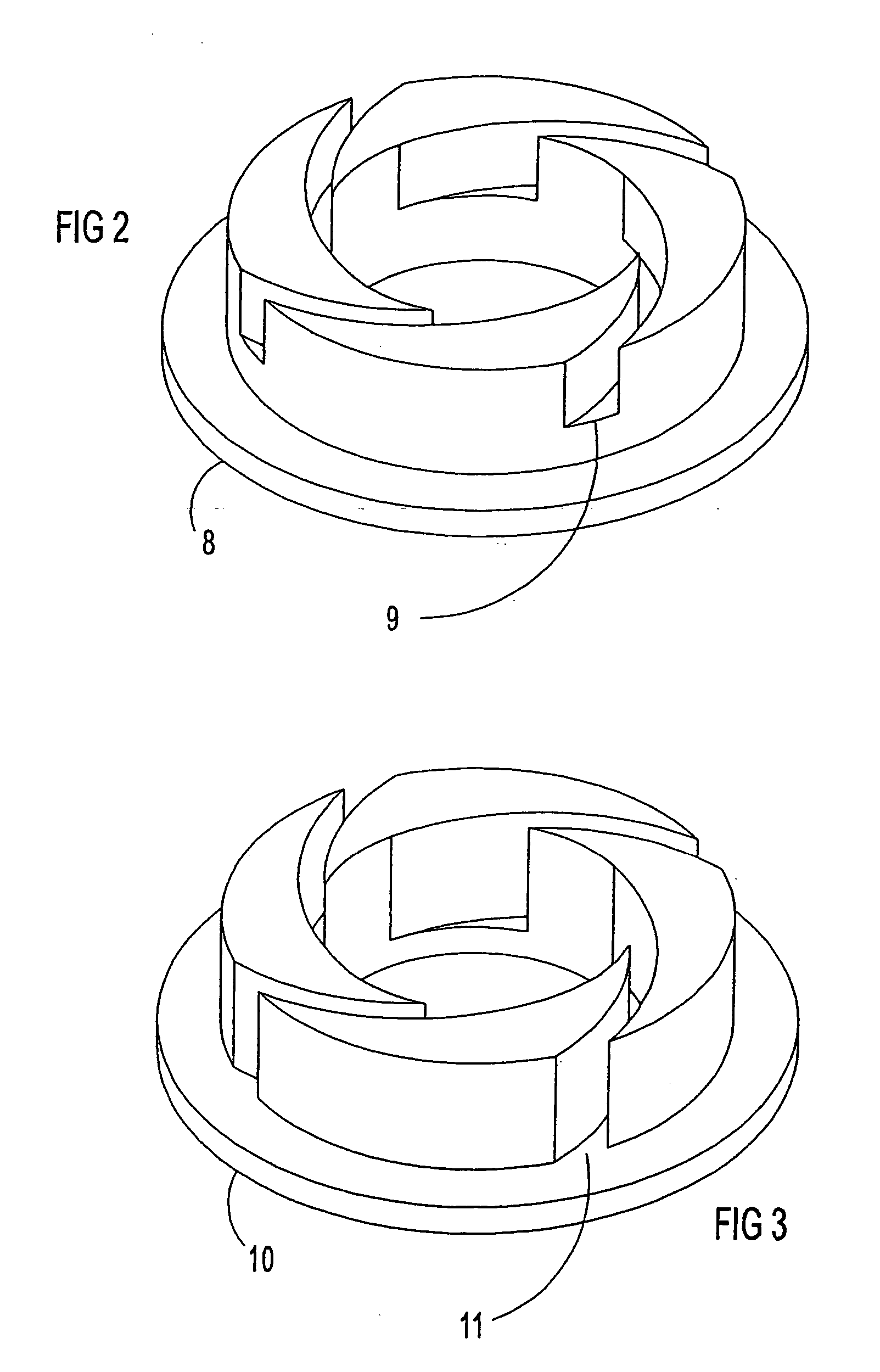
[0042] The present invention provides a new method and apparatus for drawing large quantities of a secondary fluid into a primary fluid by suction. An apparatus in accordance with the present invention may employ an eductor with a linear venturi having a cross sectional area of flow (or opening) for a primary fluid in the form of a narrow ring or in the form of a narrow rectangle with suction on either one side or both sides of the venturi opening. An eductor in accordance with the present invention expands the length of venturi suction, increases the amount of secondary fluid drawn into the primary fluid by suction, and increases efficiency

Problems solved by technology

These surcharges increase the costs of doing business.
In addition to the problem of discharging excessive contaminants to public sewage systems, animal fat rendered during the cooking process can congeal when mixed with cold water and clog up the drain lines from the kitchens to the grease traps.
When this occurs, the businesses may be shutdown and typically require routing out with a rotor cutter driven by a mechanical cable to open the lines.
When the contaminants exceed the capacity of what the bacteria can consume, they must be removed from the grease traps by vacuum trucks, or they are discharged to the public sewer, which can result in surcharges as mentioned above.
Anaerobic bacteria are not as efficient as aerobic bacteria in consuming the contaminants, and they also produce offensive odors in the process of consuming their food.
The offensive odors are prevalent around businesses with grease traps.
Attempts have been made to keep the bacteria alive by bubbling air in grease traps with limited success.
Bubbling air even with the finest diffusers creates a large amount of foam in the grease traps.
Therefore, air injection has been largely limited to short periods of time and to smaller systems.
Therefore, in the food service industry, there is a need for an efficient apparatus and method that can effectively remove particles from wastewater without the problems mentioned above, e.g. incurring surcharges for unsuccessfully meeting contaminant levels, producing offensive odors, requiring the introduction of bubbling air, thus increasing costs, etc.
Detergents and other chemicals used in the wash operation present further difficulties to the discharge problems.
The water is typically reused in the washing part of the wash cycle until it becomes apparent that the quality of the vehicle wash is no longer satisfactory.
The offensive odors are often detected by customers, especially early in the morning when the systems have been shutdown for the night.
The bubbling of air continuously can cause a foaming problem in the sumps.
In addition to the offensive odors, governmental regulations may limit the amount of contaminants that can be discharged into the public sewer systems and totally prevent discharge to the environments.
However, where the cost of water is not a factor and the public sewage system can accept certain contaminants, a complete recycling system may not be cost justified.
These steps may increase the time and money associated with the particle-removal operation.
This may lead to difficulties in certain applications.
However, it has been found that over time, particles concentrate along the inner walls of the apparatus as a result of centrifugal forces and tend to clump together and adhere to the porous walls.
This clump formation or caking impedes the exit of the carrier fluid through the porous walls.
This limits the use of the filters when tangential feeding is not possible, for example.
Because of this the size of the stream can also affect the efficiency of the venturi, with the larger diameter venturi having a decrease in efficiency.
The existing round venturi low suction-gap-length-to-volume ratio make them notoriously inefficient at transferring a secondary fluid from outside the venturi to a primary fluid flowing through the inside of the venturi.
The inefficiency is the primary reason the venturi has not received wide application in municipal wastewater treatment, the largest potential area of application that desperately needs to increase aeration efficiency because of that size and the associated high costs of energy.
However, it has been noted that the increase in head pressure of the water when the system is submerged creates a backpressure on the expanding discharge of the venturi and decreases the amount of air that can be drawn into the venturi.
The gas purification function becomes even more difficult when the gases are hot, such as exhaust gases from internal combustion engines or other combustion functions, and need to be cooled and cleaned before being discharged in the atmosphere, in an environmentally sensitive area, or in an enclosed area.
In both the gravity flowing and forced main the microorganism action in digesting the organic contaminants may cause the oxygen to become depleted.
Discharging a large amount of water into a river without sufficient dissolved oxygen to support life of fish, or other aquatic species, will cause the fish to die.
The additional energy consumed by a lift station pump for the increase in output pressure required (perhaps below 2-5 psi in most applications) to draw air into the line may typically be insignificant compared to installing additional pumps specifically for the venturi and operating them at pressures high enough to inject the output air-water mixture of the venturi downstream of the lift station pumps.
In long lines the oxygen is likely to become depleted again in route to the treatment plant because of the activity of the bacteria.
Further, when pumping liquids having dissolved gases, cavitation can occur in the pump's impeller as the liquid is drawn into the pump.
The low pressure produced by the suction of the pump causes the gases to come out of solution.

Method used


Image

  • Methods and apparatus for enhancing venturi suction in eductor mixers
  • Methods and apparatus for enhancing venturi suction in eductor mixers
  • Methods and apparatus for enhancing venturi suction in eductor mixers

Examples


second embodiment

[0141]FIGS. 27a-c illustrate three views of the eductor 320 in accordance with the present invention. FIG. 27a provides an elevation view of the primary fluid inlet (e.g. for water) end 321 of the eductor 320. FIG. 27b provides a side elevation view of the eductor 320 and identifies the primary fluid inlet (e.g. for water) 321, the secondary inlet 322 (e.g. for air), and the outlet 324. FIG. 27c provides an elevation view of the outlet end 324 of the eductor 320 from which a Sectional View A-A is taken.

[0142]FIG. 28 depicts a longitudinal Sectional View A-A of the eductor 320 taken from FIG. 27c in accordance with the present invention. The eductor 320 may comprise a primary fluid inlet (e.g. for water) 321, a circular venturi inlet 325 conically shaped on the outside, a circular venturi 326, an secondary inlet 322 (e.g. for air), a circular venturi outlet 328 expanding outward 328 and in a straight line 329 on its inside diameter, and an eductor outlet 324. The arrows indicate the ...

third embodiment

[0143]FIG. 29 depicts a three-dimensional illustration of an eductor 330 with three linear venturi forming three concentric rings with each venturi opening in the form of a narrow ring in accordance with the present invention for mixing fluids. The eductor 330 generally may comprise a primary fluid inlet (e.g. for water) 331, an secondary inlet 332 (e.g. for air), and three expanding outlets 335, 336, and 337 where the mixture (e.g. water-air) exits the outlet 334 of the eductor 330 in the form of three expanding rings. The eductor 330 can be adapted with a threaded 333 or flanged (not shown) outlet so it can be incorporated into a distribution piping system.

[0144]FIGS. 30a-30c illustrate three views of the third embodiment of the eductor 330 in accordance with the present invention. FIG. 30a provides an elevation view of the primary fluid inlet (e.g. for water) end 331 of the eductor 330. FIG. 30b provides a side elevation view of the eductor 330 and identifies the primary fluid in...

fourth embodiment

[0147]FIG. 32 depicts a three-dimensional illustration of an eductor 350 with a linear venturi opening in the shape of a thin rectangle in accordance with the present invention for mixing fluids. The eductor 350 is constructed of a housing 355 with a venturi assembly 354 inserted into the housing 355, which functionally may comprise a primary fluid inlet (e.g. for water) 351, an secondary inlet (e.g. for air) 352, and an outlet 353 where the mixture (e.g. water-air) exits the eductor 350. There are water and secondary inlets (e.g. for air) 351 and 352, respectively, on both top and bottom of the eductor 350.

[0148]FIGS. 33a-33c illustrate three views of the fourth embodiment of the eductor 350 in accordance with the present invention. FIG. 33a provides a top view of the eductor 350 indicating the primary fluid inlet (e.g. for water) 351, the secondary inlet (e.g. for air) 352, and the outlet 353 of the eductor 350 with a Sectional View B-B taken. FIG. 33b provides a side elevation vi...


PUM

PropertyMeasurementUnit
Pressureaaaaaaaaaa
Flow rateaaaaaaaaaa
Diameteraaaaaaaaaa

Abstract

An apparatus is provided for suction of a secondary fluid into a primary fluid through one or multiple gaps in contact with a venturi. The venturi imparts a high velocity on the primary fluid to flow across a gap in contact with the venturi and draw in the secondary fluid. The apparatus employs a linear venturi with the flow area, or opening, in the form of a narrow ring or narrow rectangle to increase the length of the gap in contact with the venturi. One gap is provided and positioned in contact with one side of the narrow venturi opening, or two gaps are provided having one positioned in contact each side of the narrow venturi opening. The linear venturi is housed in assemblies referred to as “eductors.” Various eductor embodiments are provided including: 1), cylindrical housings with one or multiple concentric linear venturi with openings in the form of narrow rings; 2), rectangular housings with a single rectangular linear venturi with an opening in the form of a narrow rectangle, with multiple rectangular linear venturi with inlets positioned around a primary fluid inlet to flow radially outward through the multiple venturi, with multiple rectangular linear venturi with outlets positioned around a mixing chamber to cause circulation of the flow of fluids; 3), a cylindrical housing with linear venturi with an opening in the form of a narrow ring adapted for inserting into piping; and 4), cylindrical housings with linear venturi with an opening in the form of a wide ring adapted for installation in piping.

Description

CROSS REFERENCE TO RELATED APPLICATIONS [0001] This application claims priority to U.S. Provisional Application 60 / 615,998 filed Oct. 5, 2004, entitled “Method and Apparatus for Enhancing Venturi Suction in Eductor Mixers,” by Johnny Arnaud, incorporated by reference in its entirety herein. This application is also a continuation-in-part of co-pending U.S. patent application Ser. No. 10 / 716,372, filed Nov. 18, 2003, entitled “Method and Apparatus for Mixing Fluids, Separating Fluids, and Separating Solids from Fluids,” by Johnny Arnaud, incorporated by reference in its entirety, which is a divisional of U.S. patent application Ser. No. 09 / 879,496 filed Jun. 12, 2001, entitled “Method and Apparatus for Mixing Fluids, Separating Fluids, and Separating Solids from Fluids” by Johnny Arnaud, now U.S. Pat. No. 6,669,843, which is incorporated by reference herein in its entirety.BACKGROUND OF THE INVENTION [0002] 1. Field of the Invention [0003] The invention relates to methods and apparat...

Claims


Application Information

Patent Timeline
IPC IPC(8): B01D21/24B03D1/14E21B43/12E21B43/16E21B43/34
CPCB01D21/2433B01D21/245B03D1/1425E21B43/122E21B43/128E21B43/129B03D1/1456E21B43/34E21B43/166B03D1/1431B03D1/1412Y10T137/87603Y10T137/87587
Inventor ARNAUD, JOHNNY
Owner HYDROTREAT
Learn More