[0015] In some optical switching networks, unwanted paths are necessarily blocked, in order to make it possible to connect all the desired input channels to each output channel. This is true, for example, in the selector part of the
router-selector optical switching network shown in FIG. 7. There is a controllable
polarization rotator at the exit of each
periscope (which functions as a beam combiner rather than a
beam splitter) in the selector section of the network, where light from all the input channels going into a given output channel is repeatedly combined in a
binary tree. The controllable
polarization rotator must be active, rotating the polarization of light going through it by 90 degrees, whenever the light from the left side of one
periscope enters the right side of the
periscope above it, or vice versa, in the
schematic view in FIG. 7, and this automatically blocks the unwanted light from the other side of that lower periscope from entering that upper periscope. In other optical switching networks, blocking of unwanted paths is not a necessary part of the network, but is an optional added feature which improves performance by reducing cross-talk. That is true, for example, in the 2×2 switch shown in FIG. 6.
[0016] Blocking unwanted paths increases the range of wavelengths that periscopes operate at, and decreases the tolerances for manufacture of periscopes. Thus two of the significant disadvantages of using periscopes as polarizing
beam splitters are at least partially overcome, and it becomes possible to take
advantage of the desirable features of periscopes, such as their small size.
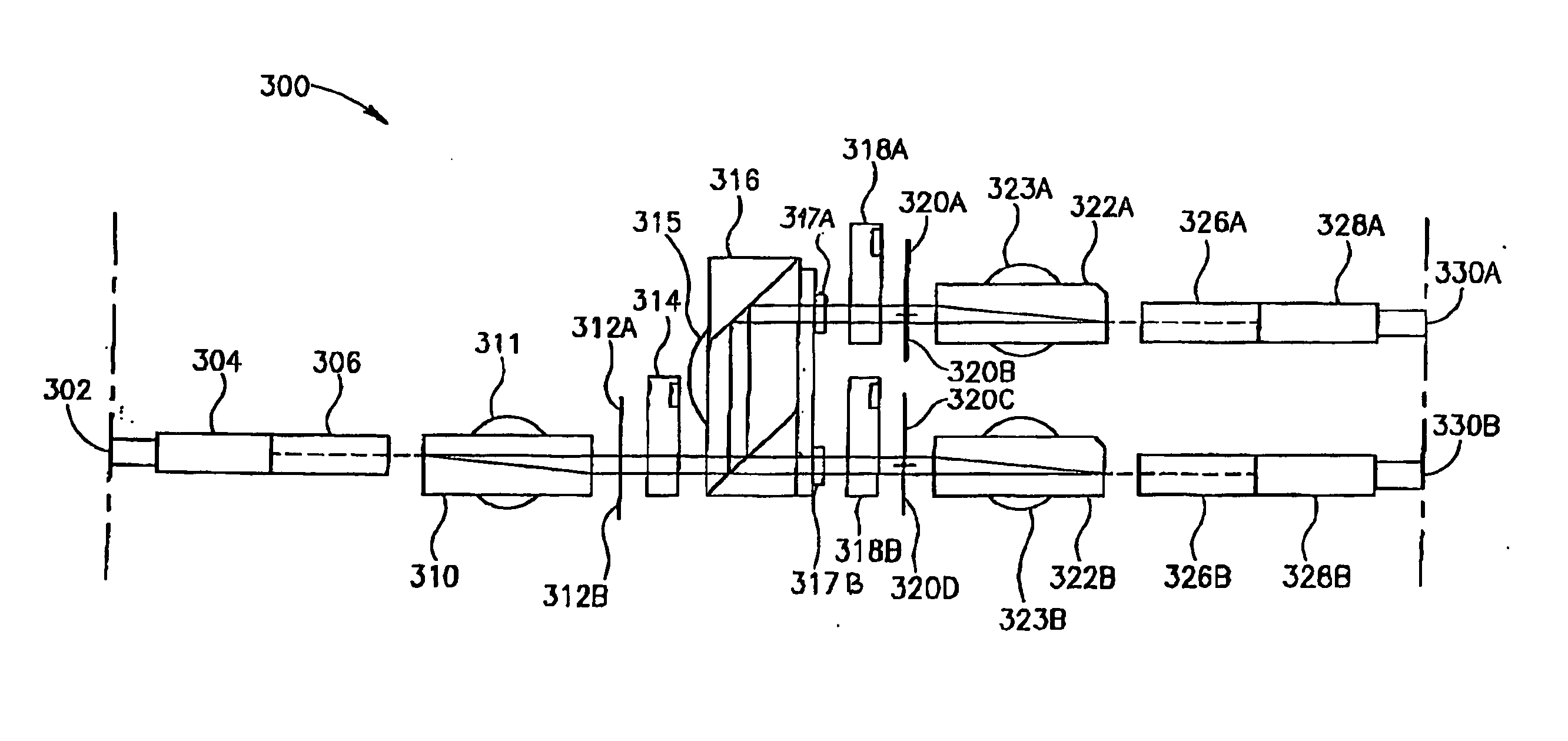
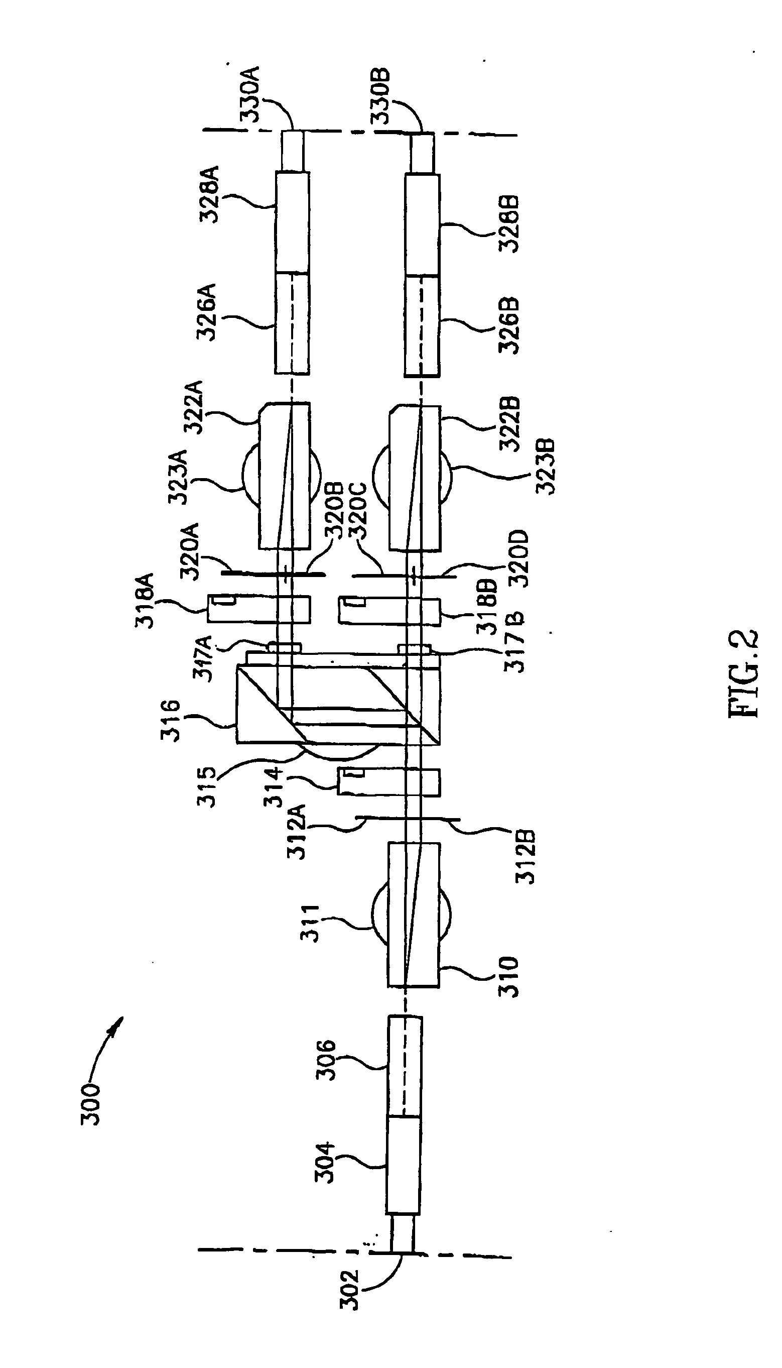
[0017] Another aspect of some embodiments of the invention concerns optical switches in which the parts of the switch are arranged in a three-dimensional configuration which is compact easy to manufacture, or otherwise advantageous. One way to accomplish this is to use half-wave plates, with principle axes oriented at an
oblique angle, before and after one or more of the controllable polarization rotators. This makes it possible to change the orientation of the principle axes of the controllable
polarization rotator, in order to make the controllable polarization rotator fit better into the
layout of the switch. In particular, if the controllable polarization rotator is a
ferroelectric crystal, or a
ceramic using the
Kerr effect, then an
electric field needs to be applied to it along one of the principle transverse axes, and a large uniform
electric field is most readily applied if the controllable polarization rotator is short in that dimension, and has large, flat electrodes attached to its sides. (Similarly, if the controllable polarization rotator uses the
Faraday effect, then a large uniform
magnetic field is most readily applied if the controllable polarization rotator is short in the direction of the field.) If the polarizing
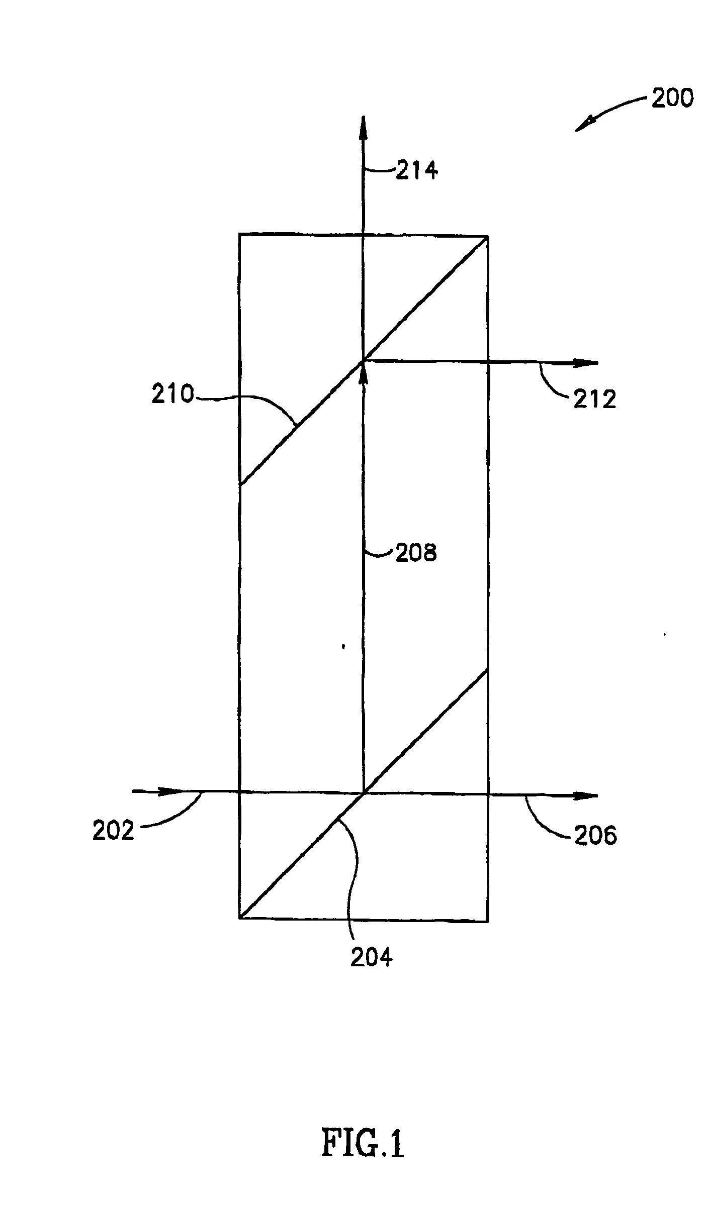
beam splitter displaces the beam in a direction parallel to the direction of polarization of the displaced beam, then it is often most convenient to use a
layout for the switch whose envelope has a rectangular cross-section, with principle axes parallel and perpendicular to the direction of polarization of the displaced beam. But the
electric field in the controllable polarization rotator, in the case of a
ferroelectric crystal or electro-optic
ceramic, is at a 45 degree angle to the direction of polarization of the light that passes through it. By placing half-wave plates, oriented with their principle axis 22.5 degrees to the direction of beam displacement, before and after the controllable polarization rotator, the principle axes of the controllable polarization rotator can be aligned with the principle axes of the rectangular cross-section of the envelope of the switch, and in particular the short dimension of the controllable polarization rotator can be aligned with the short dimension of the envelope.
[0018] Another aspect of some embodiments of the invention concerns an
optical switch or another optical configuration in which parts are mounted on rotatable bearings, such as ball and socket bearings. The parts are aligned, for example by hand or
machine, and when alignment is achieved,
ultraviolet light is applied to a UV cured
adhesive in the bearing, curing the
adhesive and fixing the bearing in place. The
adhesive can be applied to the bearing before or after the parts are aligned. Optionally, if the adhesive is applied before the parts are aligned, it is viscous enough so that the alignment will not slip spontaneously before the adhesive is cured, but is not so viscous that it is difficult to perform the alignment.
[0077] In an exemplary embodiment of the invention, said adhesive is viscous and prevent slipping of said joint when no external forces are applied to said optical element. Alternatively or additionally, said one optical is transparent to
ultraviolet light.

