
System and method for an ambient atmosphere ion thruster

Active Publication Date: 2005-08-18
NORTHROP GRUMMAN SYST CORP
View PDF4 Cites 19 Cited by
  • Summary
  • Abstract
  • Description
  • Claims
  • Application Information

AI Technical Summary

Benefits of technology

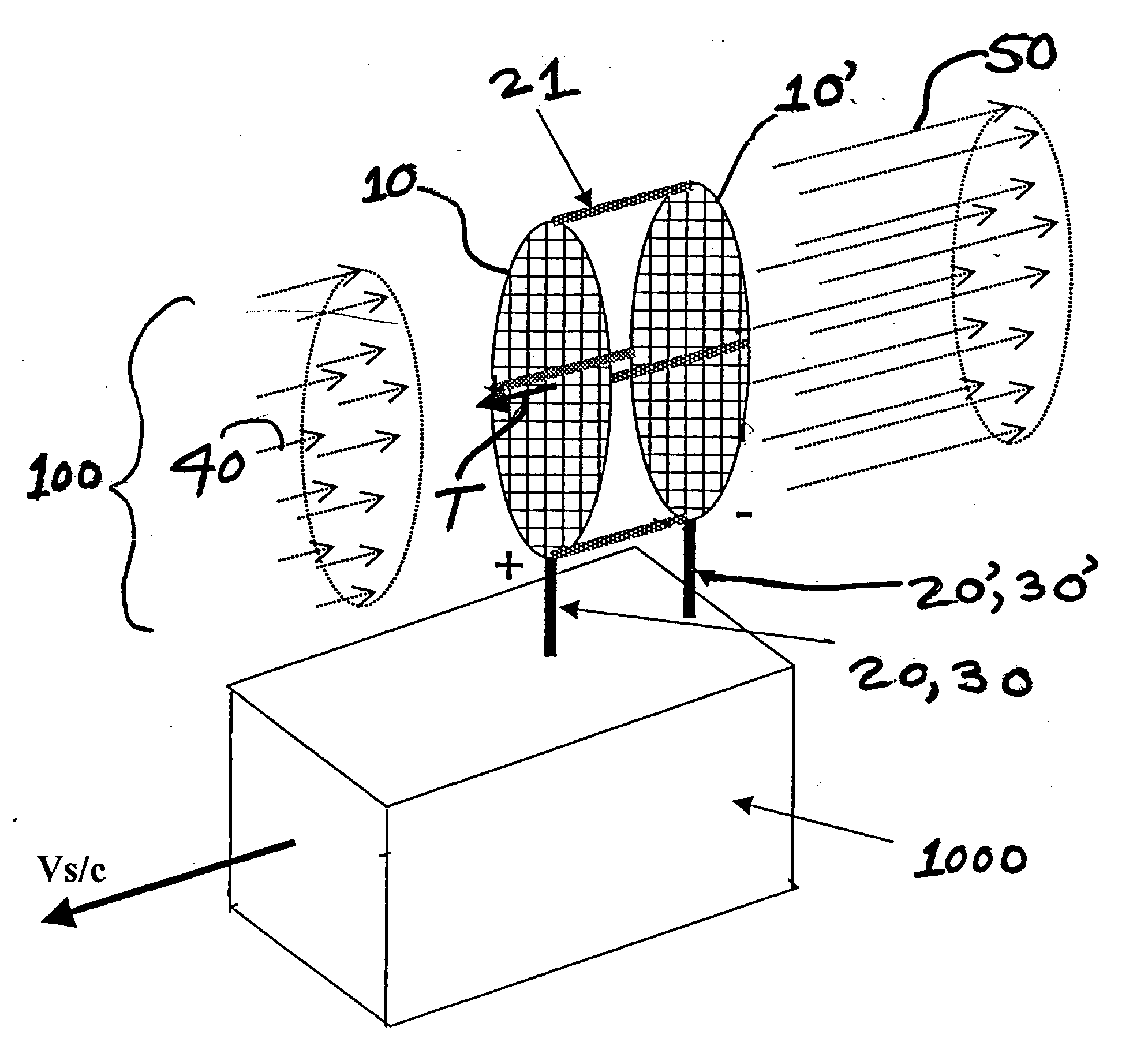
[0011] The two permeable electrical members (a forward member and a complementary aft member) of each at least one pair of permeable electrical members are separated by a distance and disposed at a parallel or an approximately parallel orientation for intercepting any ambient atmosphere ions, atoms, and molecules between the forward member and the aft member from the vicinity of the craft. The two members of each at least one pair of permeable electrical members are electrically charged with respect to one another (i.e., one is positively charged while the other is negatively charged) for accelerating the ions by the therebetween developed electrostatic field. The at least one pair of permeable electrical members may be mechanically connected by at least one electrically insulating support structure to the craft. The at least one electrically insulating support structure may have at least one electrical feed. Each member of the at least one pair of permeable electrical members comprises a high ratio of orifice area to lattice area for maximizing the mass flux throughput. The craft experiences a reactionary force from the accelerated ions, thereby providing a significant net thrust and / or torque for propelling the craft as well as for controlling the attitude of the craft.
[0013] Advantages of the present invention include, but are not limited to, significant performance, cost, reliability, and safety benefits by reducing or eliminating on-board propellants and any associated handling / support hardware and software from the craft, development of more thrust per unit weight, development of thrust in any direction with respect to the craft, operation in close proximity to any celestial body having a sensible atmosphere (e.g., Mars, Venus, Jupiter, Saturn, and Europa), and operation in the absence of sunlight. As such, new low Earth orbit (“LEO”) missions (i.e., orbits having an altitude in a range of less than approximately 1000 km, geosynchronous transfer orbit (“GTO”) missions, and planetary missions) may be enabled by the present invention. Many satellite missions, such as reconnaissance missions, Earth resource mapping, space-based missile defense, atmospheric research, and ionospheric research, may be improved by maintaining a continuous lower Earth orbit which is provided by the present invention.

Problems solved by technology

Orbital decay, due to atmospheric drag, presents a major life-limiting issue for satellites, especially for reconnaissance and remote sensing satellites, which cannot be feasibly refueled to replenish propellants expended during propulsive reboosting.
Such lower Earth orbit inherently involves greater atmospheric drag.
Other related art space propulsion systems have employed gravitational gradients and geomagnetic fields for attitude stabilization; however, these methods do not provide the net thrust that is necessary for altitude control.
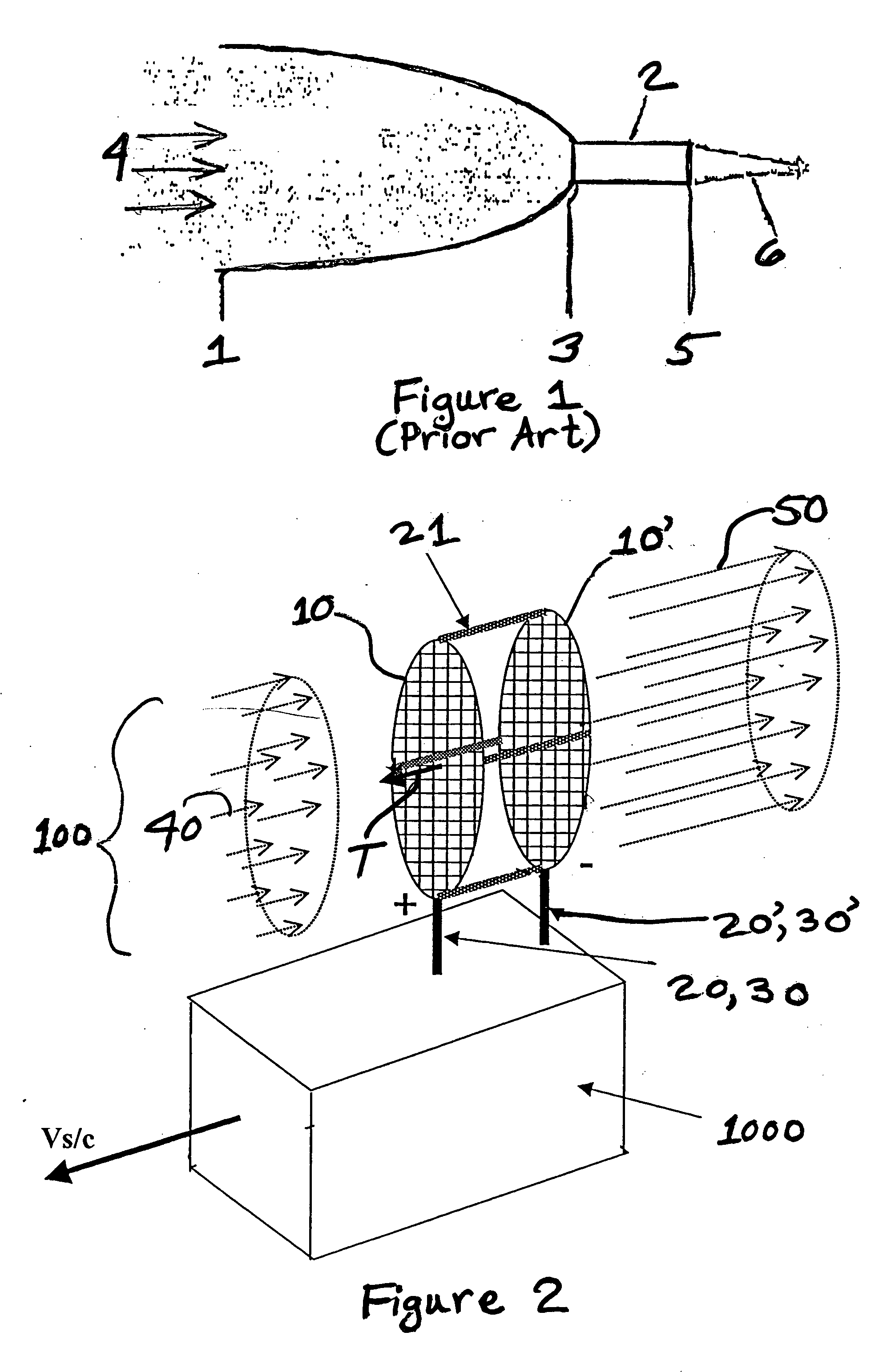
Such scoops have been known to impart considerable drag, because they decelerate the intake mass flow 4.
“Ionic breeze” air purifiers use electric devices for moving ambient air; however, such devices are not known to have been applied to space propulsion systems nor has their use been suggested for use in the sparse atmosphere of the near-Earth space environment.
Lifters have not been found to be practical for any significant transportation purpose, because they require substantially high voltage (e.g., >15 kV) for operation.
Moreover, the ionic breeze devices being implemented in air purifiers, as well as toy lifters, rely on the relatively dense atmosphere found near Earth's surface; and they have not been suggested nor demonstrated for operation in the sparse atmosphere of the near-Earth space environment (i.e., in the altitude range of at least 200 km above Earth's mean surface).
While photon reflection has been also used as a “mass-less” method for providing thrust (e.g., solar sails and laser levitation of particles), such thrust has been demonstrated as being extremely low, and any thrust vectoring as being limited to a 180° arc centered on the vector of incident radiation.

Method used


Image

  • System and method for an ambient atmosphere ion thruster
  • System and method for an ambient atmosphere ion thruster
  • System and method for an ambient atmosphere ion thruster

Examples


first embodiment

[0017]FIG. 2 is a perspective view of at least one ambient atmosphere ion thruster comprising at least one pair of permeable electrical members, the at least one thruster being mounted to a craft by at least one insulating support structure having at least one electrical feed (conduit), and ambient atmosphere constituents being intercepted by the at least one pair of permeable electrical members comprising an intake mass flux, and a reaction force being experienced by the craft from accelerated ions comprising an exhaust mass flux, in accordance with the present invention.

second embodiment

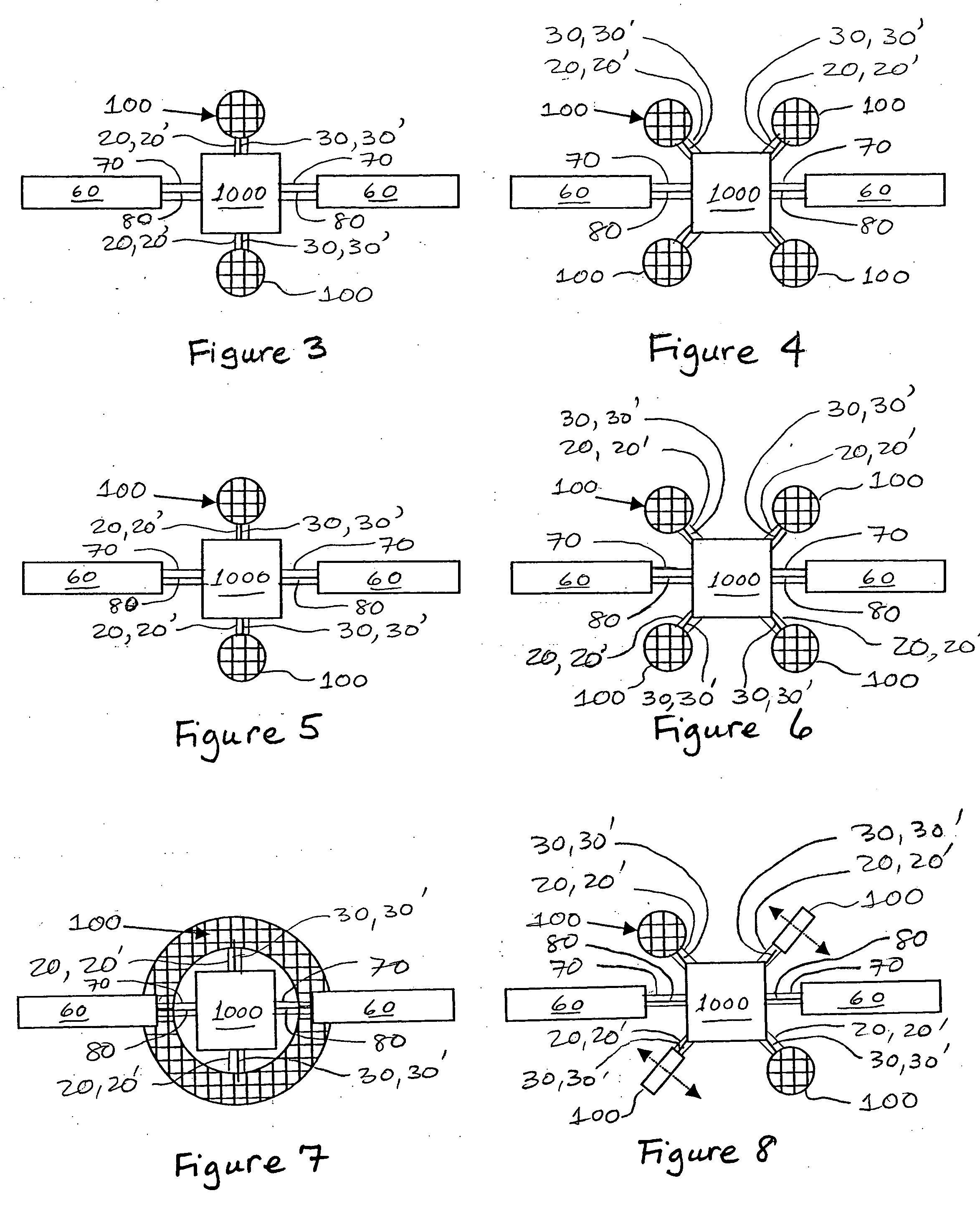
[0018]FIG. 3 is a rear view taken along a velocity vector of two ambient atmosphere ion thrusters, fixedly mounted to opposing sides of a craft for boost, deboost, and attitude control along a single axis, in accordance with the present invention, with typical craft appendages, such as a solar array or radio frequency (RF) antenna being shown for reference only.

third embodiment

[0019]FIG. 4 is a rear view taken along a velocity vector of four ambient atmosphere ion thrusters, fixedly mounted to opposing vertices of a craft for boost, deboost, and attitude control along two axes, in accordance with the present invention, with typical craft appendages, such as a solar array or radio frequency (RF) antenna being shown for reference only.


PUM


Abstract

A system and a method for an ambient atmosphere ion thruster having a pair of permeable electrical members for accelerating ambient atmosphere ions which enter the thruster due to a craft's relative velocity. Neutral ambient atmosphere molecules in the intake mass flux may also be ionized and subsequently accelerated by the pair of permeable electrical members. Acceleration of any entering mass comprises an exhaust mass flux which then produces a net thrust. Such net thrust is then vectored by configuring and orienting the thrusters for imparting axial and lateral accelerations as well as pitch, yaw, and roll controls. The present invention is operational in proximity to any celestial body having a sensible atmosphere during a portion of the free trajectory or during orbiting at altitude. Useful net thrust is thereby produced without need for carrying reaction mass onboard a spacecraft.

Description

TECHNICAL FIELD [0001] The present invention relates to spacecraft dynamics and spacecraft control systems and methods. More particularly, the present invention relates to spacecraft propulsion and spacecraft control systems and methods. Even more particularly, the present invention relates to satellite propulsion and satellite control systems and methods. BACKGROUND ART [0002] Rocket thrusting in space environments (e.g., at altitudes greater than 200 km above Earth's surface) has presumed that a propellant must be carried on board as a reaction mass (i.e., a fuel source). Related art space vehicles are typically propelled by carrying a reaction mass, chemically reacting or heating, or applying kinetic energy to, the mass and subsequently expelling the reacted mass, thereby propelling (i.e., thrusting) the space vehicle. Such related art propulsion systems usually comprise a fuel or reaction mass source and an energy source, which may be a chemical source, a photovoltaic source, a ...

Claims


Application Information

Patent Timeline
IPC IPC(8): B64G1/40F03H1/00
CPCF03H1/0012B64G1/405B64G1/413
Inventor DRESSLER, GORDON A.
Owner NORTHROP GRUMMAN SYST CORP
Learn More