Optical device for optical communication

an optical communication and optical signal technology, applied in the direction of optical waveguide light guide, optical elements, instruments, etc., can solve the problems of large deformation of the optical signal-to-noise ratio (osnr) of the generated data light, difficult to individually monitor/control all wavelength channels, and complex device configuration. achieve high duty rate, accurate and stable operation, and easy control

Active Publication Date: 2005-09-01
FUJITSU LTD
View PDF16 Cites 10 Cited by
  • Summary
  • Abstract
  • Description
  • Claims
  • Application Information

AI Technical Summary

Benefits of technology

[0016] It is an object of the present invention to provide an optical device for generating stable data light with a high OSNR and narrow pulse width in an arbitrary bit rate.
[0018] According to the present invention, since optical pulses are not directly generated by modulating by intensity, optical pulses whose pulse width is narrower than the operational limit of an electrical circuit can be generated. Since the present invention requires no cavity configuration when optical pulses are generated, stable optical pulses with narrow pulse width that are strong against the manufacturing limit of the cavity and an environmental change, such as a temperature change and the like can be generated.
[0019] By the present invention, the generation of data light with high duty rate and pulse width of pico-seconds or subpico-seconds without being restricted by the frequency of a modulation signal, whose control is easy, which accurately and stably operates in an arbitrary repetition frequency can be realized. The downsizing and cost reduction of a data light source device can be realized, and its reliability can be improved.

Problems solved by technology

However, if the number of wavelengths increases, it becomes difficult to individually monitor / control all wavelength channels.
Furthermore, it has a problem that the optical signal-to-noise ratio (OSNR) of the generated data light greatly degrades in return for the improved duty rate.
However, although the oscillation of data light by these mode locked lasers has an advantage of easily generating optical clocks with high duty rate, it has also a problem that its device configuration becomes complex and its size becomes large.
However, it is unrealistic as a light source that generates the above-described optical clock with an arbitrary and accurate frequency, from the practical point of view, such as a manufacturing technology, a product price, a device size and the like.
Although the conventional method for applying an optical gate to CW light using an intensity modulator and generating data light can be easily realized by a configuration simpler than a mode locked laser pulse light source, it has a problem that it is difficult to generate optical pulses with high duty rate and the like.

Method used


Image

  • Optical device for optical communication
  • Optical device for optical communication
  • Optical device for optical communication

Examples


Embodiment Construction

[0035] The preferred embodiments of the present invention are described below with reference to the drawings.

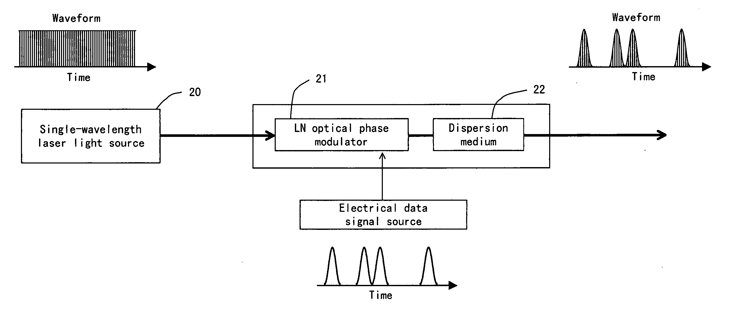
[0036]FIG. 4 shows the configuration of the first preferred embodiment of the present invention. FIG. 4 shows the configuration of a short-pulse data light source adopting a modulation method according to the first preferred embodiment of the present invention. An LN (LiNbO3) optical phase modulator 21 applies frequency chirp to light outputted from a single-wavelength laser light source 20 by an electrical data signal. Then, if a dispersion medium 22 compensates for the frequency chirp, specifically adjusts the phase relationship of the light in such a way that its phase does not change on a time axis, a solitary wave (data light) can be obtained. For the single-wavelength laser light source 20, semiconductor DFB laser or DBR laser is used. The optical phase modulator induces frequency chirp to CW light. For the optical phase modulator, a 10-40 Gb / s electrical signal is use...


PUM

PropertyMeasurementUnit
wavelengthaaaaaaaaaa
frequencyaaaaaaaaaa
repetition frequencyaaaaaaaaaa

Abstract

An optical phase modulator made of lithium niobate or the like phase-modulates the output light of a single-wavelength laser light source 20 that emits CW light, and the phase-modulated light is inputted to a dispersion medium 22. The positive chirp and negative chirp of light to which frequency chirp is applied by phase modulation draw near in the dispersion medium and an optical pulse is generated.

Description

BACKGROUND OF THE INVENTION [0001] 1. Field of the Invention [0002] The present invention relates to an optical device for optical communication, and more particularly to a method for generating data light with high duty rate, a device thereof and applications thereof. [0003] 2. Description of the Related Art [0004] Currently in an optical fiber communication system, a wavelength-division multiplexing (WDM) multiplexing signal light whose bit rate per wavelength channel is 10 Gb / s or 40 Gb / s in a wavelength domain is put into practical use. The WDM system is characterized in that communication capacity can be easily increased by increasing the number of wavelengths. However, if the number of wavelengths increases, it becomes difficult to individually monitor / control all wavelength channels. There is also an optical time-division multiplexing (OTDM) system extending capacity by multiplexing data light with narrow pulse width against a bit interval though its bit rate is 10 Gb / s or 40...

Claims


Application Information

Patent Timeline
Patent Type & Authority Applications(United States)
IPC IPC(8): G02F1/01G02F2/00H04B10/25H04B10/2507H04B10/508H04B10/516H04B10/524H04B10/54H04B10/556H04B10/58H04B10/61H04J14/08
CPCH04B10/25137H04B10/572H04B10/299
Inventor FUTAMI, FUMIOWATANABE, SHIGEKI
Owner FUJITSU LTD
Why Eureka
Try Eureka