
Ultraviolet, narrow linewidth laser system

a laser system and ultraviolet technology, applied in laser details, optical devices for lasers, active medium materials, etc., can solve the problems of poor reliability of even well-engineered uv ion lasers in industrial environments, poor device efficiency, and high cost of ownership, so as to improve the output of ultraviolet lasers, simplify the configuration, and the effect of improving the outpu

Inactive Publication Date: 2005-09-01
SPECTRA PHYSICS
View PDF10 Cites 25 Cited by
  • Summary
  • Abstract
  • Description
  • Claims
  • Application Information

AI Technical Summary

Benefits of technology

[0008] Accordingly, one object of the present invention is to provide improved ultraviolet laser output using a simplified, robust configuration.
[0009] Another object of the present invention is to improve the power output and durability of CW lasers producing ultraviolet laser wavelengths.

Problems solved by technology

Such devices, however are very inefficient, requiring 10's of kW electrical input for <1 W optical output.
Reliability of even well-engineered UV ion lasers in industrial environments has been shown to be poor, with high cost of ownership.
Phase-matching limitations in the most practical UV nonlinear crystals mean that usually four steps are required to convert the fundamental IR output into the 200 nm range.
Furthermore, efficient CW nonlinear conversion requires high optical intensities, which practically, can only be obtained inside an active or passive resonator.
Although intra-cavity second harmonic generation (ICSHG) is efficient and fairly common in CW lasers, additional frequency conversion steps are known to be increasingly difficult, costly and inefficient.
Thus, a 200 nm system based exclusively on DPSS lasers loses most of the DPSS reliability, efficiency, complexity and cost advantages.
Although diode pumping of these tunable lasers has been demonstrated, high brightness, high reliability diodes with the requisite short wavelengths are not yet available with enough power to allow scaling to the tens of watts level required for useful harmonic generation.
Ti:sapphire lasers can also emit CW radiation in the 750-800 nm requirement, and have been scaled to well over 20 W, but these lasers have significant disadvantage of requiring a CW diode-pumped green laser as a pump source, resulting in greater cost and complexity and lower overall electrical system efficiency.

Method used


Image

  • Ultraviolet, narrow linewidth laser system
  • Ultraviolet, narrow linewidth laser system
  • Ultraviolet, narrow linewidth laser system

Examples


Embodiment Construction

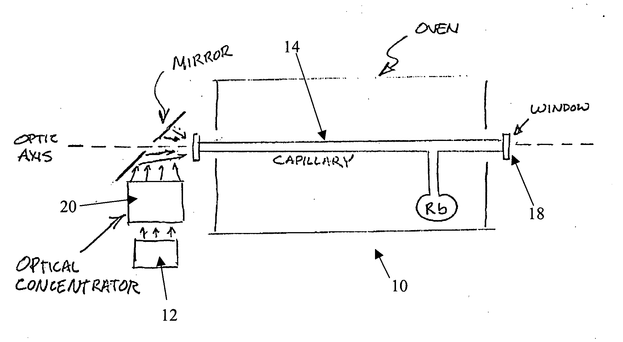
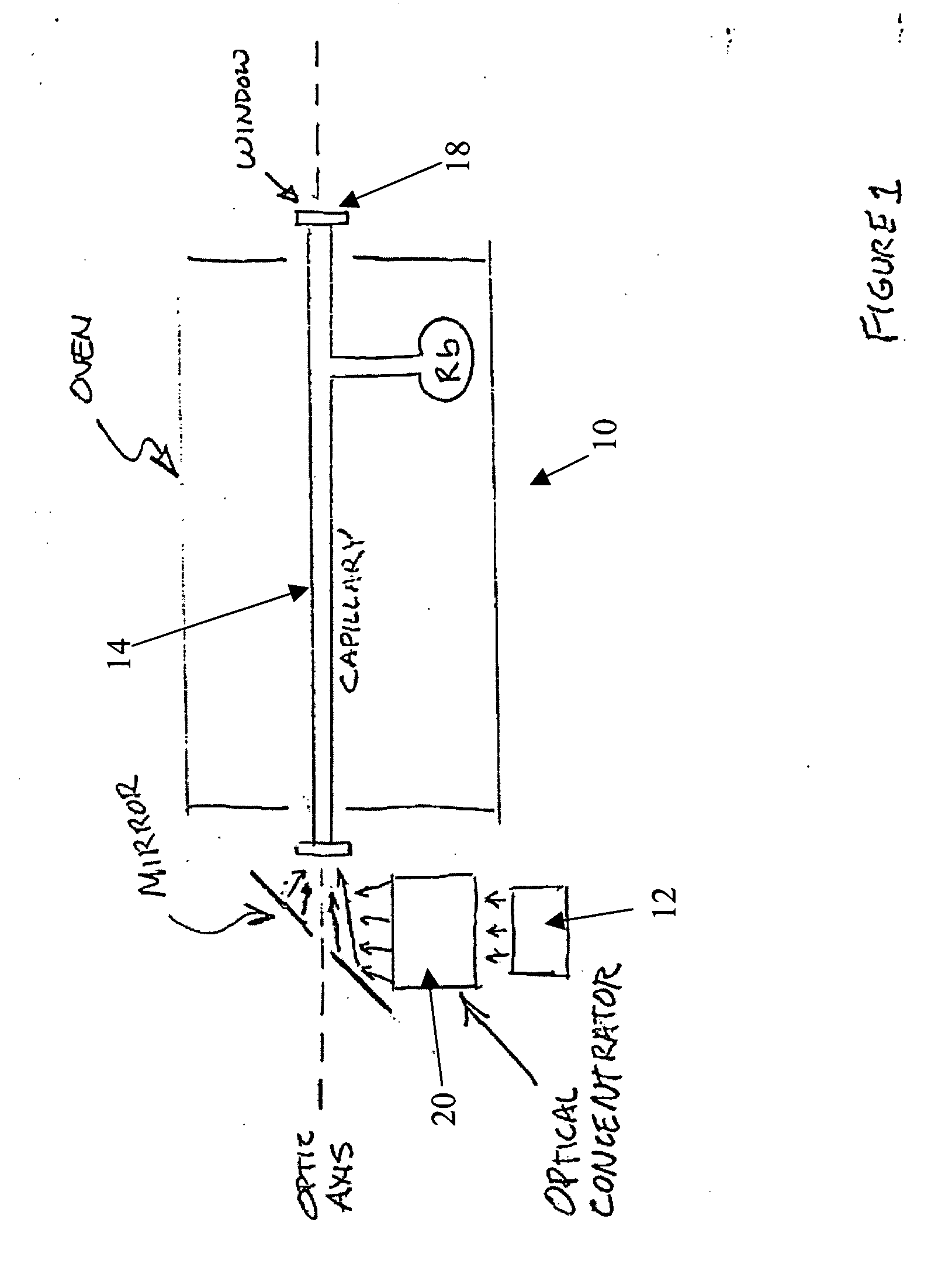
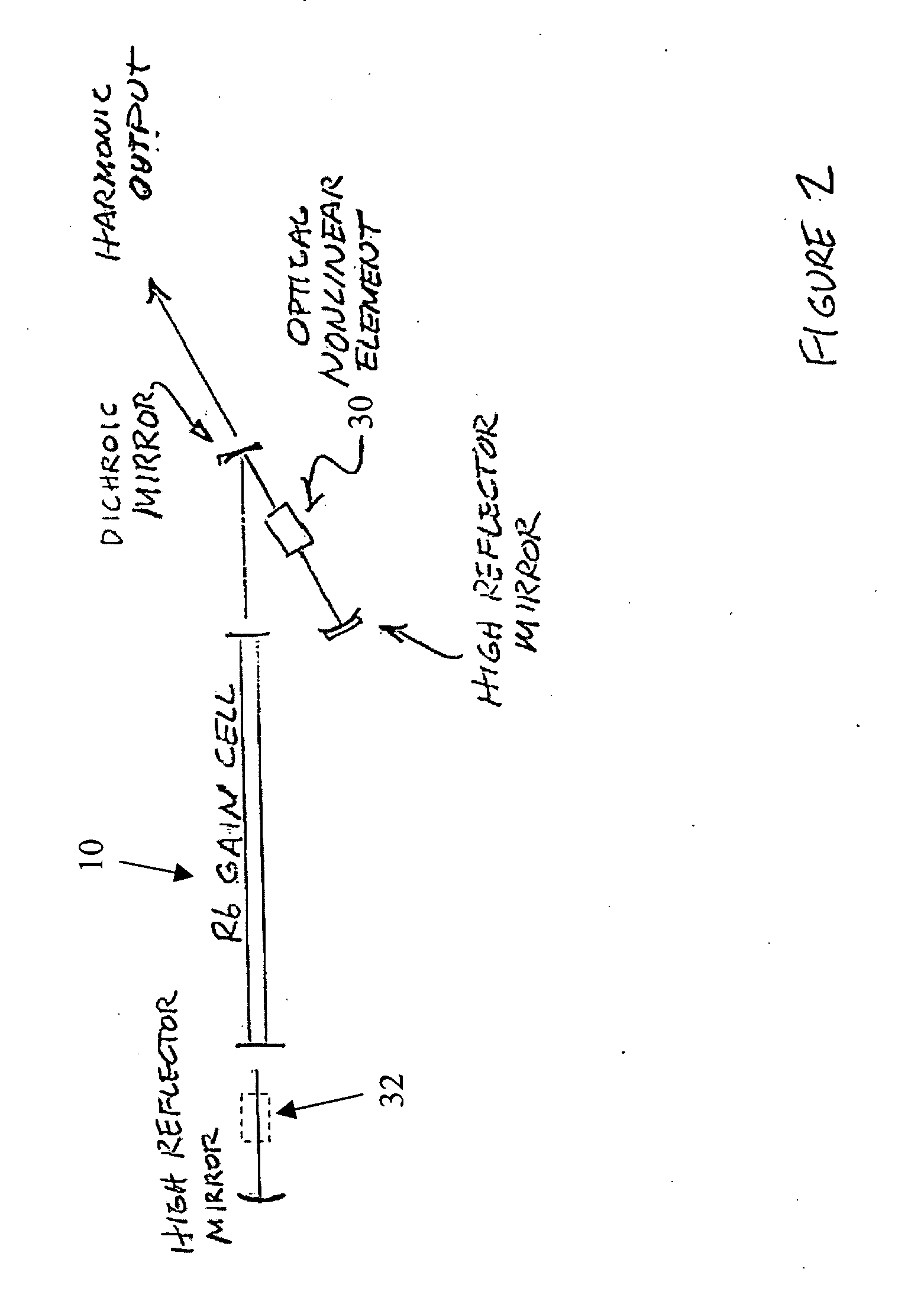
[0036] The present invention is directed to methods and techniques for providing laser systems based on intra-cavity harmonic conversion of a diode-pumped gas laser. In particular, intra-cavity conversion to the fourth harmonic of a diode-pumped Rb vapor laser is disclosed, that is especially useful for semiconductor inspection, where a sub-200 nm CW source of power output on the order of at least 200 mW is desired. Although not limited to the following, application of the intra-cavity harmonic conversion techniques to other high gain CW sources operating near or just under 800 nm are included within the scope of the invention.

[0037] Thus 795 nm rubidium vapor laser exhibits several notable advantages with respect to intra-cavity frequency conversion into the sub-200 nm range. Thus the third harmonic of the fundamental radiation is at 265 nm and the fourth harmonic is at 198.7 nm, both of which are highly useful for semiconductor inspection and other applications. The high gain of ...


PUM


Abstract

A laser device is provided for generating an ultraviolet output. The device comprises a laser having at least one diode-pumped alkali metal vapor gain cell for generating a near infrared laser output, and at least two optically-nonlinear crystals. In one particular embodiment, the laser uses a Rb gas cell and generates radiation at a wavelength of about 199 nm and at least 200 mW of power with a linewidth of less than 10 GHz. In another embodiment, narrow linewidth UV light is generated at 265 nm.

Description

CROSS-REFERENCE TO RELATED APPLICATIONS [0001] The present application claims the benefit of priority to co-pending U.S. Provisional Application Ser. No. 60 / 534,480 (Attorney Docket No. UVRB474978) filed Jan. 7, 2004. This application is incorporated herein by reference for all purposes.BACKGROUND OF THE INVENTION [0002] 1. Field of the Invention [0003] This invention relates to laser equipment and more specifically, to ultraviolet (UV) laser systems with specific wavelength output and narrow linewidth. [0004] 2. Description of Related Art [0005] As semiconductor devices achieve higher integration densities, optical systems for wafer and mask inspection as well as other manufacturing operations require shorter operating wavelengths. Although a variety of lasers can be adapted for these purposes the most generally applicable laser for semiconductor inspection would be a continuously operating (CW) device with a narrow linewidth (≦10 GHz) and a wavelength near one of the currently pre...

Claims


Application Information

Patent Timeline
IPC IPC(8): H01S3/00H01S3/0941H01S3/109H01S3/22H01S3/227H01S3/23
CPCH01S3/005H01S3/094053H01S3/094057H01S3/2316H01S3/09415H01S3/109H01S3/227H01S3/0941
Inventor PETERSEN, ALAN B.KAFKA, JAMES D.
Owner SPECTRA PHYSICS
Learn More