Cryogenic cogeneration system

a cogeneration system and cryogenic technology, applied in the direction of mechanical power devices, mechanical equipment, machines/engines, etc., can solve the problems of hydroelectricity production, significant negative impact on the environment, and inconvenient operation,

Inactive Publication Date: 2005-09-15
BLOCK ZINA +1
View PDF7 Cites 32 Cited by
  • Summary
  • Abstract
  • Description
  • Claims
  • Application Information

AI Technical Summary

Benefits of technology

[0025] Additional objects and advantages of the invention will be set forth in the description which follows, and in part will be obvious from the description, or may be learned by practice of the invention. The objects and advantages of the invention may be realized and obtained by means of apparatus, methods, and combinations particularly pointed out in the appended claims.

Problems solved by technology

Heretofore, numerous methods and apparatuses have been developed for production of mechanical and electrical energy, however difficulties and limitations are inherent in all of them.
It is predicted that this will have a significant negative impact on our environment within the next 50 years.
Plants utilizing dams / water reservoirs, to produce hydroelectricity, also will impact our environment due to the necessity to flood surrounding inhabited land resources.
In addition, water resources are depleted to suffice electrical demands.
The accidents in Chernobyl, in the Soviet Union, and 3 Mile Island, in the United States, have proven Nuclear power through history to be very unhealthy and potentially fatal to people within surrounding areas.
An effective means of disposing nuclear waste has not been established.
Nuclear power, still consumes uranium, and has limited capacity due to the necessity to operate at lower pressures for safety reasons.
Chlorofluorohydrocarbon (CFC) emissions from existing refrigeration and air conditioning systems have been depleting our Earth's ozone layer, which is believed to be the cause of many illnesses attributed to harmful radiation entering our atmosphere.
Further, growing problems associated with energy production and supplies that are continuing to decrease the health of our planet include negative effects as a result of the greenhouse effect, the depletion of the Earth's ozone layer, nuclear waste disposal, and the many other adverse effects, including loss of life and land, that are attributed to the fossil fuel industry (war, oil tanker spills, offshore drilling, land destruction as a result of coal mining, etc.) and land flooding from the building of dams.
Economic problems also will continue to grow as consumable energy resources become more scarce and as a result of the cost of the necessary upgrading of old, power generation and grid systems in developed countries.
In addition, as China's and India's industrial development continues to grow at an accelerated pace power consumption and demand increases.
Fossil fuel burning, and many other presently known mechanical engines in use today also present problems for the defense Industry.
One problem is that all of these engines release residual heat that is detectable by the infrared heat sensors.
But as fossil fuel plants do, bio mass generation also emits harmful gases into our atmosphere, again negatively impacting our environment.
(b) Wind turbine generation is probably the best existing technology implemented today but has limited capacity capabilities, requires considerable initial investments, utilizes considerable amount of land and it is not aesthetically pleasing to many.
(c) Solar thermal and solar photovoltaic power generation is limited due to its dependency on weather conditions and availability of sunlight.
Collector arrays again have to consume large surface areas of property to generate a reasonable amount of power.
This also requires extra expense and maintenance costs attributed to the necessary installation of large thermal or chemical energy storage systems, that are typically coupled with them.
Also unlike biomass, wind turbines, and solar, this alternative requires consumption of hydrogen and it is not economically efficient to completely modify our infrastructure to make our society dependent on hydrogen, as it is, dependent on fossil fuel today.
Present technology requires costly energy consumption to liquify the hydrogen.
However, both these technologies require mechanical motor driven compressor(s) and / or pump(s) that consume more energy than the system can produce in net shaft work output which requires an external power generation source for supplemental energy input, and the internal latent heat of the system is rejected to an external heat sink rendering it wasted energy.
Significant problems and limitations accompany all such technology, For example, the Cryocar LN2000 extracts stored liquid nitrogen an open loop system which consists of an evaporator, superheater and an expansion engine to create shaft work coupled to propel and / or power the vehicle.
In similarity to the hydrogen fuel cell technology, this system, as it is presently developed, is not economically efficient.
Further, being that it requires completely modifying our infrastructure to make our society dependent on nitrogen, as opposed to the current dependency on fossil fuel today, its practicality is very limited.
Further, such prior technology requires costly energy consumption, that can include fossil fuel, to liquefy the nitrogen.

Method used


Image

  • Cryogenic cogeneration system
  • Cryogenic cogeneration system
  • Cryogenic cogeneration system

Examples


Embodiment Construction

[0034] Reference will now be made in detail to the present preferred embodiments of the invention as illustrated in the accompanying drawings.

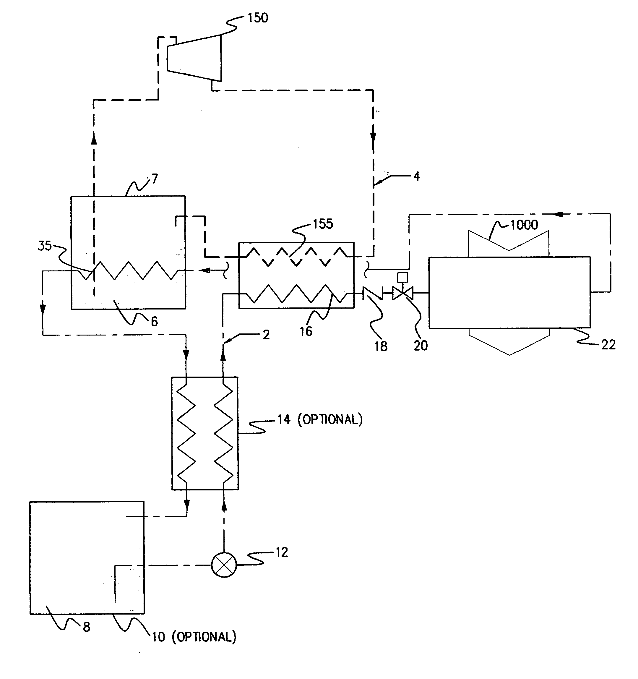
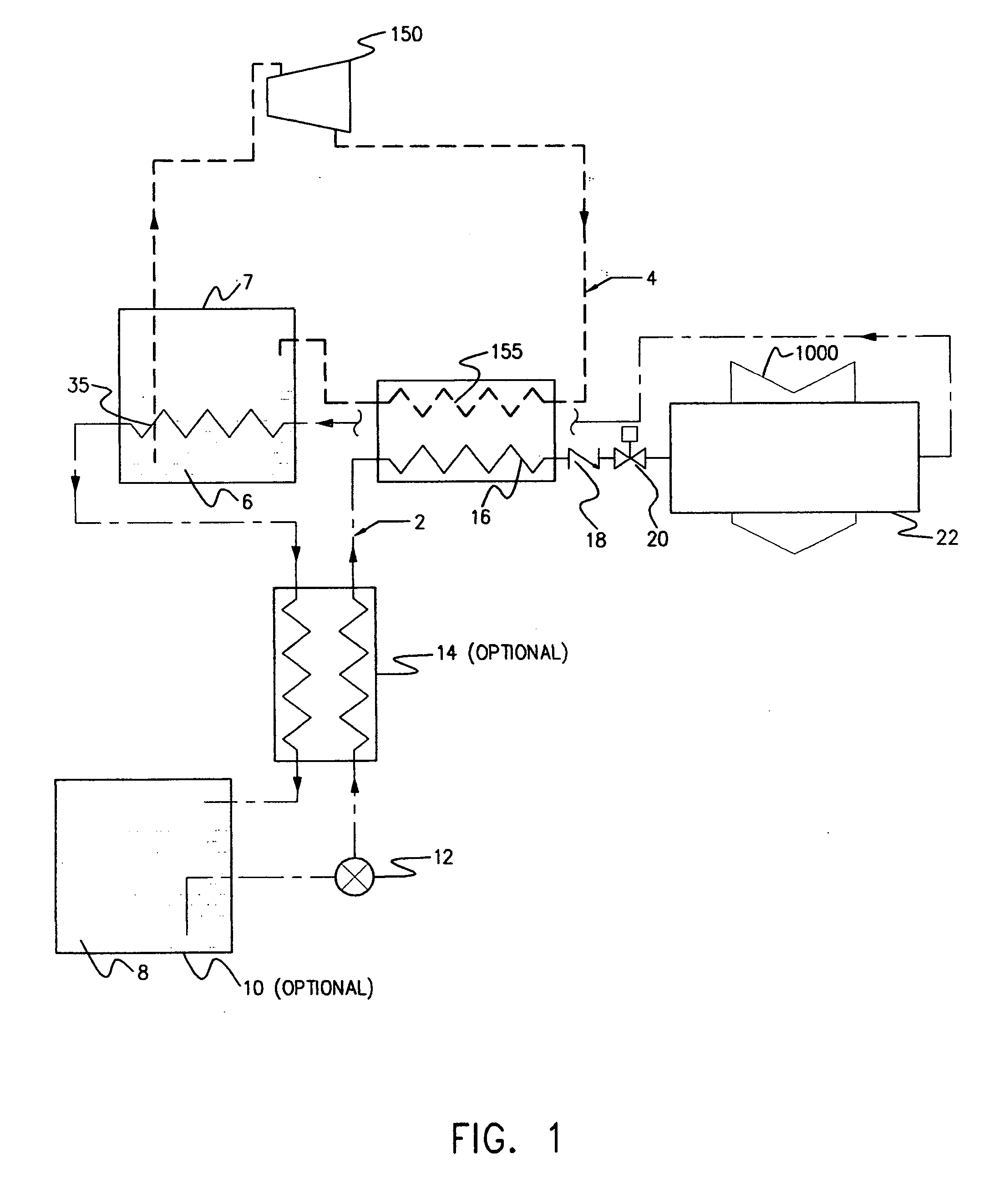
[0035] The cryogenic and thermal source cogeneration system of the present invention includes both method and apparatus including an array of heat exchanger(s), flow regulation device(s), compression system(s) and expansion engines that are assembled to integrate synchronized thermodynamic and non thermodynamic processes for the extraction of heat from geo-thermal (natural internal heat sources below the surface of the earth) or solar-thermal (natural heat sources above the Earth's surface) energy sources and for the conversion of this thermal energy (heat) into mechanical energy. This system may be utilized primarily to drive generators for the production of electricity but other applications include benefits from the net mechanical work produced by this system. This system also has many cogeneration applications that can be utilized as an a...


PUM


Abstract

A cryogenic and thermal source cogeneration method for converting energy from a heat source, through a cryogenic heat transfer process, into mechanical and / or electrical energy, comprising, utilizing a vapor compression cycle (2) to absorb heat from the heat source and, utilizing a Rankine cycle (4) for energy transfer, for converting thermal energy to mechanical and / or electrical energy.

Description

RELATED APPLICATION(S) [0001] This continuation application claims the benefit of the earlier filed U.S. patent application Ser. No. 10 / 961,942 entitled “Cryogenic Cogeneration System” filed Oct. 8, 2004. The earlier filed application is related to and claims priority from U.S. Provisional Patent Application Ser. No. 60 / 511,292, filed Oct. 14, 2003.TECHNICAL FIELD [0002] This invention relates to methods and apparatuses for converting thermal energy to mechanical and / or electrical energy. BACKGROUND ART [0003] Heretofore, numerous methods and apparatuses have been developed for production of mechanical and electrical energy, however difficulties and limitations are inherent in all of them. For example, electrical power plants utilizing high priced fossil fuel to generate electricity are emitting greenhouse gases that scientists claim to be the greatest contributor to the global warming problem. It is predicted that this will have a significant negative impact on our environment with...

Claims


Application Information

Patent Timeline
Patent Type & Authority Applications(United States)
IPC IPC(8): F01K25/08F02G1/04F03G6/00
CPCF01K25/08F02G1/04F03G6/005Y02E10/46
Inventor SHIRK, MARKSTORCK, GARYWELGEL, WESLEY
Owner BLOCK ZINA
Why Eureka
Try Eureka