
QWIP with electron launcher for reducing dielectric relaxation effect in low background conditions

a dielectric relaxation and electron launcher technology, applied in the field of quantum well infrared photodetector (qwip), can solve the problems of dielectric relaxation effect, non-uniform field distribution cost, flow through, etc., and achieve the effect of reducing both resistance (r) and capacitance (c) of qwip and effectively reducing the dielectric relaxation

Active Publication Date: 2005-09-22
GULA CONSULTING LLC
View PDF4 Cites 8 Cited by
  • Summary
  • Abstract
  • Description
  • Claims
  • Application Information

AI Technical Summary

Benefits of technology

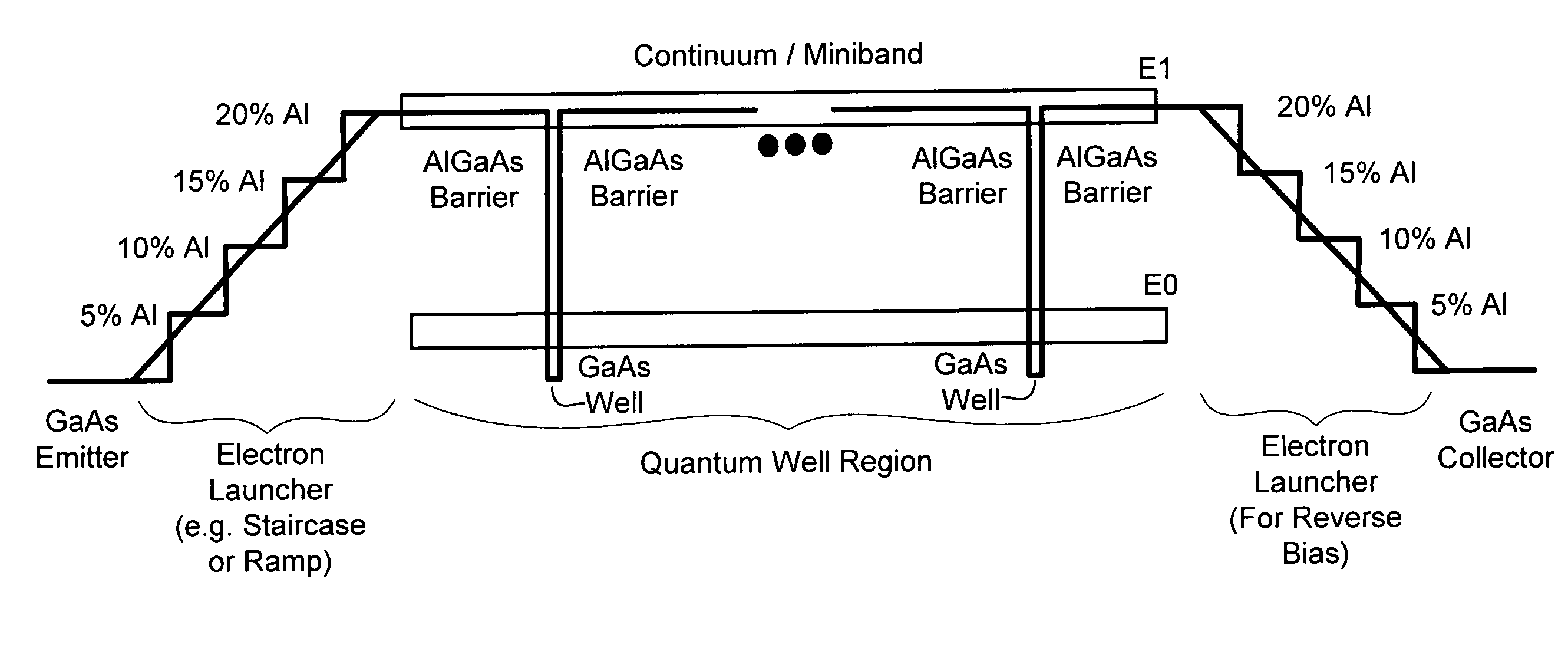
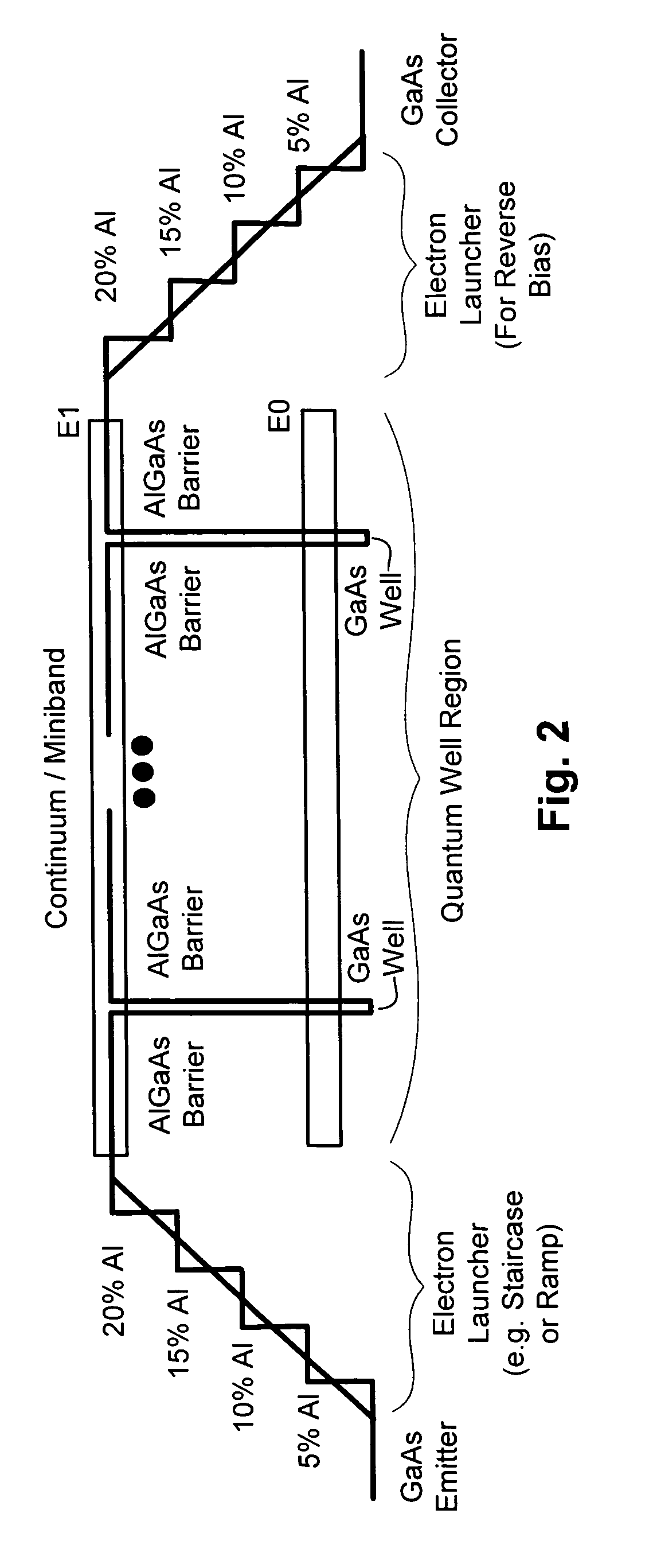
The present invention provides a quantum well infrared photodetector (QWIP) device that includes an emitter contact layer and a stack of quantum wells. The device includes an electron launcher with a plurality of steps to enable dark electrons to move quickly from the emitter contact layer into the stack, thereby reducing resistance and capacitance. The quantum wells have a width of about (40 Å to 80 Å) and the barriers have a thickness of about (450 Å to 650 Å). The device can detect multiple wavelengths and has a blocking layer to suppress tunneling current. The technical effects of the invention include reducing the dielectric relaxation effect, reducing the RC time constant, and improving the device's performance.

Problems solved by technology

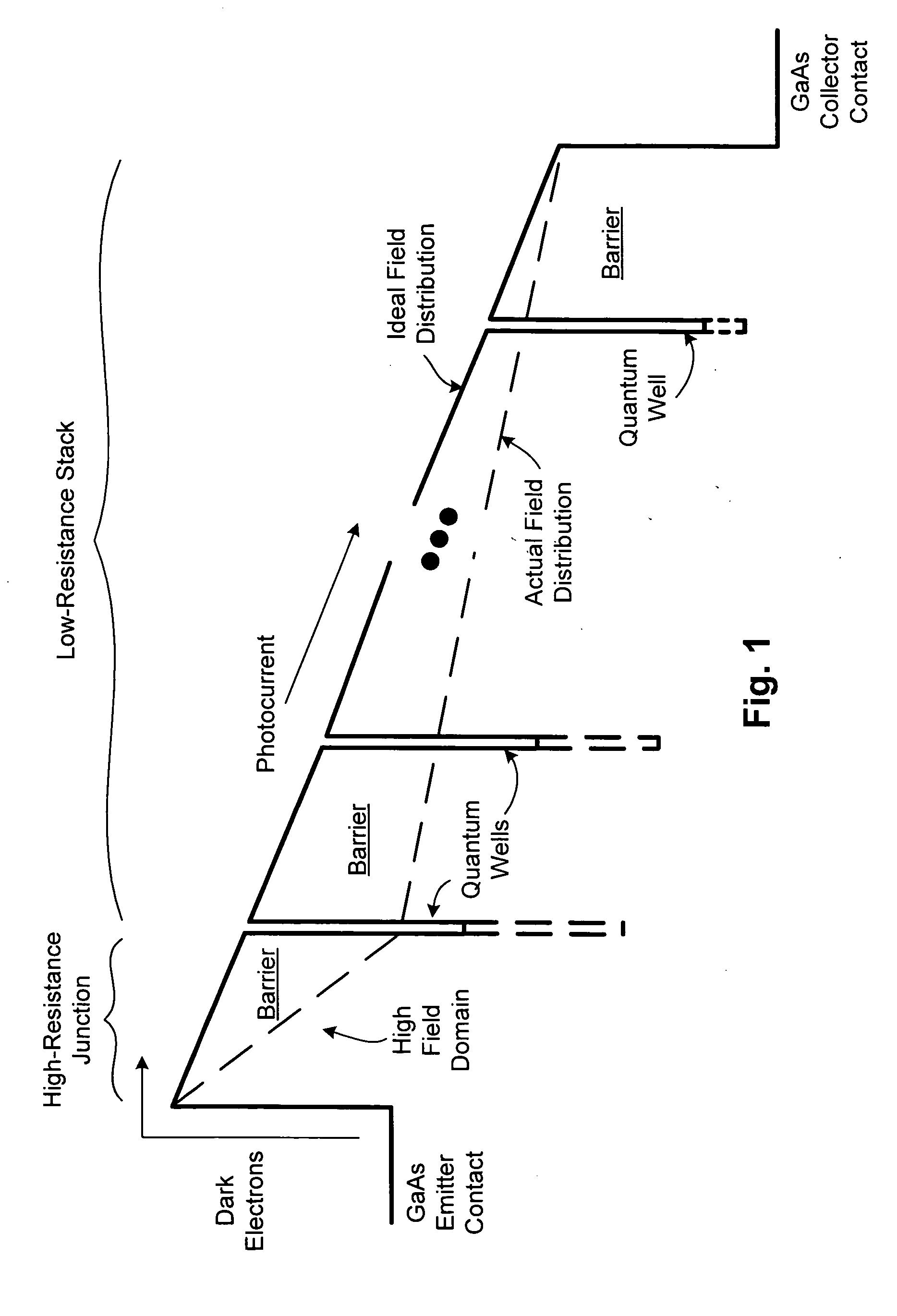
In accordance with Ohms' Law, therefore, the current flow through the device remains constant, but only at the cost of a non-uniform field distribution.
One adverse consequence of the non-uniform field distribution is the dielectric relaxation effect, particularly in low temperature and low background conditions.
In low-background conditions, the high resistance of the high field domain causes delay in refilling the space charge buildup.
In addition, such slow response times may render narrow light pulses undetectable by the QWIP.
Such results can be highly undesirable.

Method used


Image

  • QWIP with electron launcher for reducing dielectric relaxation effect in low background conditions
  • QWIP with electron launcher for reducing dielectric relaxation effect in low background conditions
  • QWIP with electron launcher for reducing dielectric relaxation effect in low background conditions

Examples


Embodiment Construction

[0022] Embodiments of the present invention provide a QWIP design that effectively eliminates or otherwise reduces the dielectric relaxation effect, thereby enhancing QWIP responsivity. This can be achieved by providing a staircase or ramp from the emitter to the active quantum well region, which acts as a low resistance mechanism for launching electrons from the emitter into active quantum well region. As such, the typically high resistance point between the emitter and the active quantum well region is effectively lowered. Having reduced the dominant resistance component of the overall QWIP resistance, the active quantum well region can be configured with thicker barriers, which enable a desirable sharp spectral response. In short, grading the barrier at the emitter to launch electrons, both lowers the choke point resistance dramatically as well as restores detector sensitivity.

[0023] The present invention has many applications. For example, QWIPs configured with an electron laun...


PUM


Abstract

A QWIP structure is disclosed that includes a graded emitter barrier and can further be configured with a blocked superlattice miniband. The graded emitter barrier effectively operates to launch dark electrons into the active quantum well region, thereby improving responsivity. A graded collector barrier may also be included for reverse bias applications. The configuration operates to eliminate or otherwise reduce image artifacts or persistence associated with dielectric relaxation effect in low-background applications.

Description

FIELD OF THE INVENTION [0001] The invention relates to quantum well infrared photodetector (QWIP) technology, and more particularly, to a QWIP structure configured with a graded barrier for launching electrons from the emitter into the active quantum well region. BACKGROUND OF THE INVENTION [0002] A quantum well designed to detect infrared (IR) light is called a quantum well infrared photodetector (QWIP). QWIPs operate by photo-excitation of electrons between a ground state and an excited state of its quantum wells. In more detail, a quantum well absorbs IR photons. This absorption of IR photons photo-excite electrons from the ground state to the excited state of each quantum well. The excited states of the quantum wells making up a QWIP are close to or within an energy transport band (sometimes referred to as the continuum or a miniband). A voltage externally applied to the QWIP operates to sweep out the photo-excited electrons from the quantum wells, thereby producing a photocurre...

Claims


Application Information

Patent Timeline
Patent Type & Authority Applications(United States)
IPC IPC(8): H01L29/06H01L29/15H01L31/0304H01L31/0352H01L31/101
CPCB82Y20/00H01L29/155Y02E10/544H01L31/035236H01L31/101H01L31/03046
Inventor SUNDARAM, MANIREISINGER, AXEL R.
Owner GULA CONSULTING LLC
Learn More