Polymers their preparation and uses

Inactive Publication Date: 2005-09-22
CAMBRIDGE DISPLAY TECH LTD
View PDF5 Cites 20 Cited by
  • Summary
  • Abstract
  • Description
  • Claims
  • Application Information

AI Technical Summary

Benefits of technology

[0008] Another approach is development of novel blue electroluminescent materials. For example, WO 00/55927, which is a development of WO 99/48160, discloses a blue electroluminescent polymer of formula (a):
[0009] In essence, the separate polymers disclosed in WO 99/48160 are combined into a single molecule. The F8 repeat unit is provided for the purpose of electron injection; the TFB unit is provided for the purpose of hole transport; and the PFB repeat unit is provided as the emissive unit.
[0010] WO 99/54385 and EP 1229063 disclose copolymers of fluorenes and amines.
[0011] It is an object of the present invention to provide a means for increasing the lifetime of polymers for use in an optical device above that of prior art polymers. It is a further object of the invention to provide a long-lived polymer for use in an optical device, particularly a long-lived blue electroluminescent material. It is a yet further object of the invention to provide a means for increasing the thermal stability of prior art polymers.
[0012] The present invent

Problems solved by technology

One drawback with existing polymer OLED displays relevant to this development is the relatively short lifetime of blue emissive materials known to date (by “lifetime” is meant the time for the brightness of the OLED to halve at constant current when operated under DC drive).
However, the advantage of selecting a cathode that i

Method used


Image

  • Polymers their preparation and uses
  • Polymers their preparation and uses
  • Polymers their preparation and uses

Examples


examples

Monomer Examples

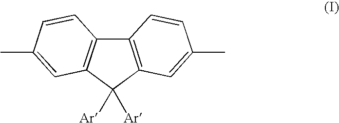
[0040] Monomers according to the invention were prepared in accordance with the scheme below:

Monomer Example M1: 2,7-dibromo-9,9-diphenylfluorene

[0041]

[0042] In a 3 L flange flask fluorenone (100.006 g, 0.555 mol), phosphorus pentoxide (110.148 g, 0.776 mol) and trimethylphosphate (1200 mL) were mixed. Under mechanical stirring, a solution of bromine (63 mL, 1.23 mol) in trimethylphosphate (200 mL) was quickly added. This clear solution was then heated for 22 hours at 120° C. The mixture was allowed to cool to room temperature, then poured into 3 L of water. When sodium thiosulfate was added (50.045 g) the mixture turned yellow. Stirring was maintained for 1 hour then the yellow solid was filtered. This solid was heated in methanol to remove the mono-brominated compound and gave 176.183 g (98% pure by HPLC, 94% yield).1H NMR (CDCl3) 7.73 (2H, d, J 2.0), 7.61 (2H, dd, J 7.6, 2.0), 7.36 (2H, d, J 8.0); 13C NMR (CDCl3) 142.3, 137.5, 135.3, 127.9, 123.3, 121.8, 109.8...

polymer example p1

[0048] A blue electroluminescent polymer according to the invention was prepared in accordance with the process of WO 00 / 53656 by reaction of 9,9-di-n-octylfluorene-2,7-di (ethylenylboronate) (0.5 equivalents), 2,7-dibromo-9,9-diphenylfluorene (0.35 equivalents) and N,N′-di(4-bromophenyl)-N,N′-di(4-n-butylphenyl)-1,4-diaminobenzene (0.15 equivalents) to give polymer P1:

Device Example

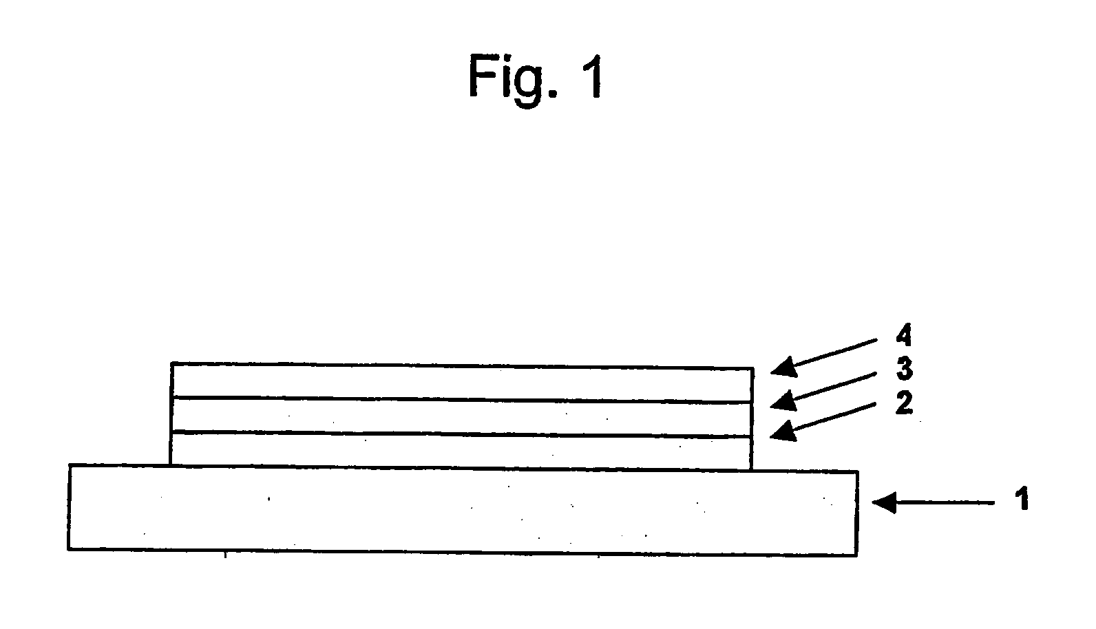
[0049] Onto indium tin oxide supported on a glass substrate {available from Applied Films, Colorado, USA) was deposited a layer of PEDT / PSS, available from Bayer® as Baytron P® by spin coating. A layer of polymer P1 was deposited over the PEDT / PSS layer by spin-coating from xylene solution. Onto the polymer P1 was deposited a cathode consisting of a first layer of lithium fluoride, a second layer of calcium and a third, capping layer of aluminium.

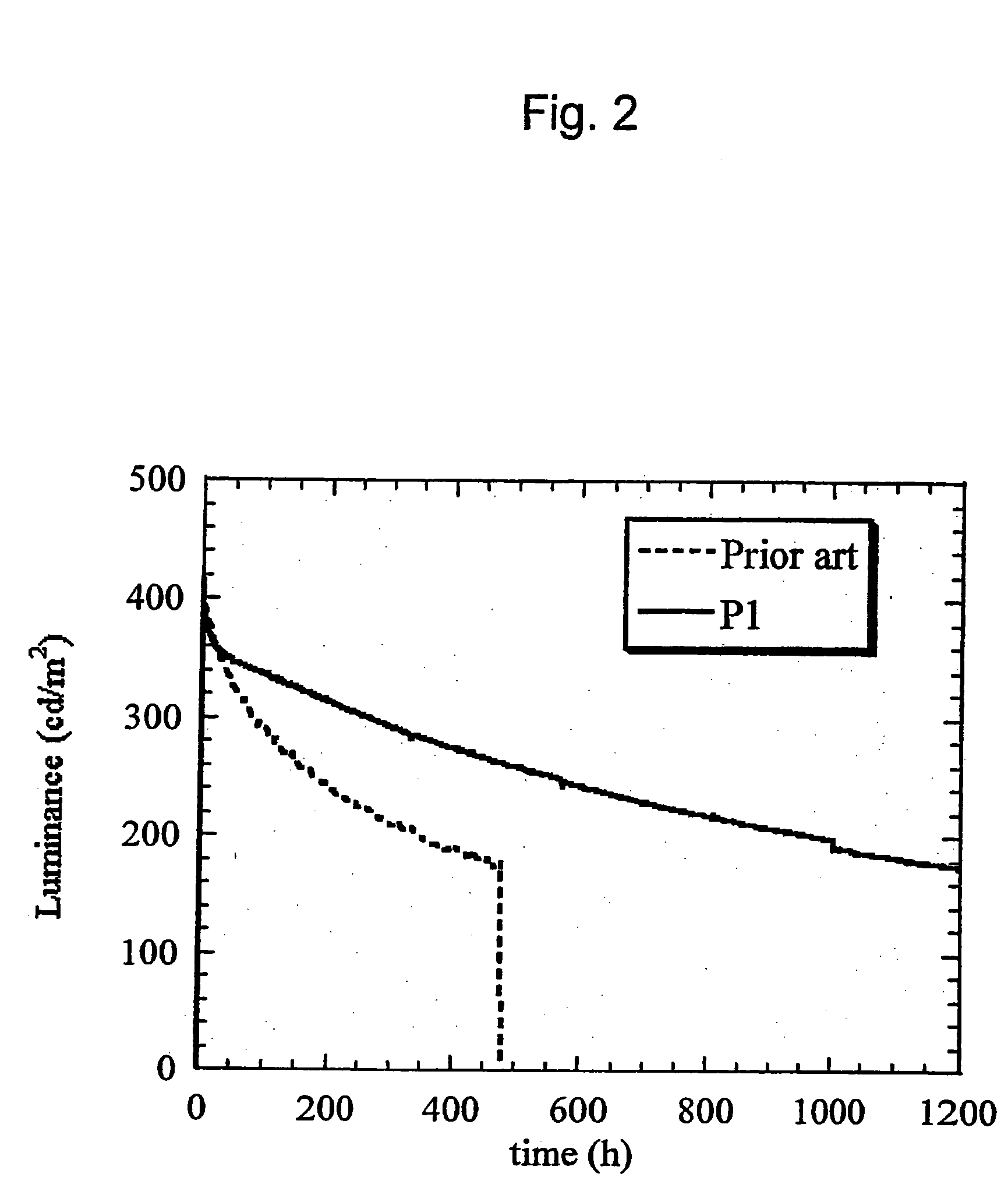
[0050] For the purpose of comparison with P1, an identical device was prepared except that the electroluminescent polymer comprised 10% TFB repeat units (fu...


PUM

PropertyMeasurementUnit
Fractionaaaaaaaaaa
Wavelengthaaaaaaaaaa

Abstract

A polymer for use in an optical device comprising a first, optionally substituted, repeat unit of formula
and a second, optionally substituted, repeat unit of formula
wherein each Ar and Ar′ is the same or different and comprises an optionally substituted aryl or heteroaryl group and optionally a third, optionally substituted, repeat unit in a molar ratio of no greater than 5%, the third repeat unit having a formula —Ar—N(Ar)—Ar— and having a single nitrogen atom in its backbone.

Description

FIELD OF THE INVENTION [0001] The invention relates to materials for optical devices, in particular organic electroluminescent devices, and the control of their physical and electronic properties. BACKGROUND OF THE INVENTION [0002] One class of opto-electrical devices is those using an organic material for light emission or detection. The basic structure of these devices is a light emissive organic layer, for instance a film of a poly (p-phenylenevinylene) (“PPV”) or polyfluorene, sandwiched between a cathode for injecting negative charge carriers (electrons) and an anode for injecting positive charge carriers (holes) into the organic layer. The electrons and holes combine in the organic layer generating photons. In WO 90 / 13148 the organic light-emissive material is a polymer. In U.S. Pat. No. 4,539,507 the organic light-emissive material is of the class known as small molecule materials, such as (8-hydroxyquinoline) aluminium (“Alq3”). In a practical device one of the electrodes is...

Claims


Application Information

Patent Timeline
IPC IPC(8): C08F222/40H01L51/50C08G61/02C08G61/12C08G73/02C09K11/06H01L51/00H01L51/30
CPCC08G61/02C08G61/12C08G73/026C09K11/06C09K2211/1416Y10S428/917C09K2211/1433H01L51/0039H01L51/0043H01L51/0059H01L51/5012C09K2211/1425C09K2211/1408H10K85/115H10K85/151H10K85/631H10K50/11
Inventor O'DELL, RICHARDTOWNS, CARLTIENEY, BRIANO'CONNOR, STEPHENGRIZZI, ILARIAFODEN, CLARE L.PATEL, NALINKUMARLEADBEATER, MARK L.MURTAGH, LORRAINE
Owner CAMBRIDGE DISPLAY TECH LTD
Why Eureka
Try Eureka