

Electronic ballast with closed loop control using composite current and voltage feedback and method thereof
a closed loop, current and voltage feedback technology, applied in the direction of electric variable regulation, process and machine control, instruments, etc., can solve the problems of street lamps that cannot safely light up the street, the control of power presents special difficulties, and the insufficient illumination of lamps
- Summary
- Abstract
- Description
- Claims
- Application Information
AI Technical Summary
Benefits of technology
Problems solved by technology
Method used
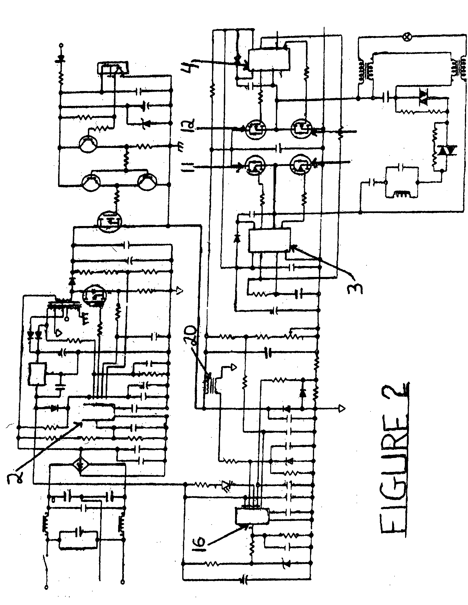
Image

Examples
example 1
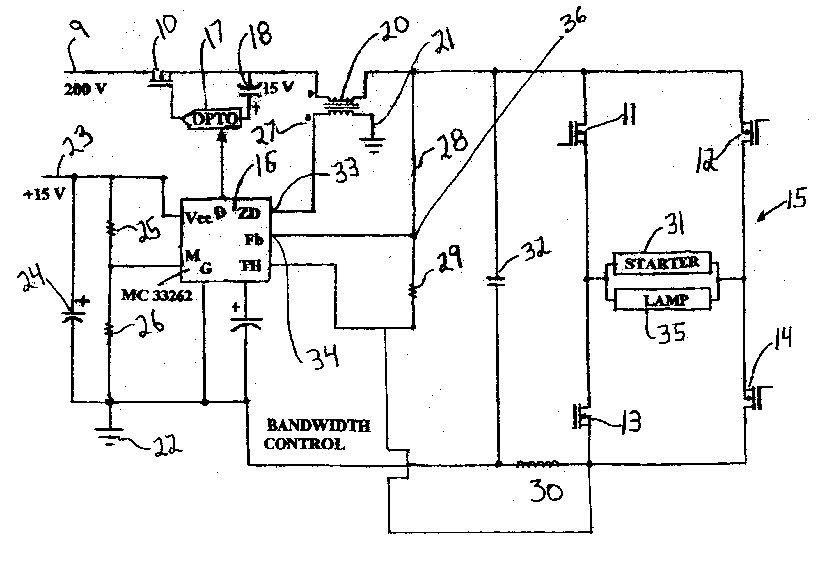
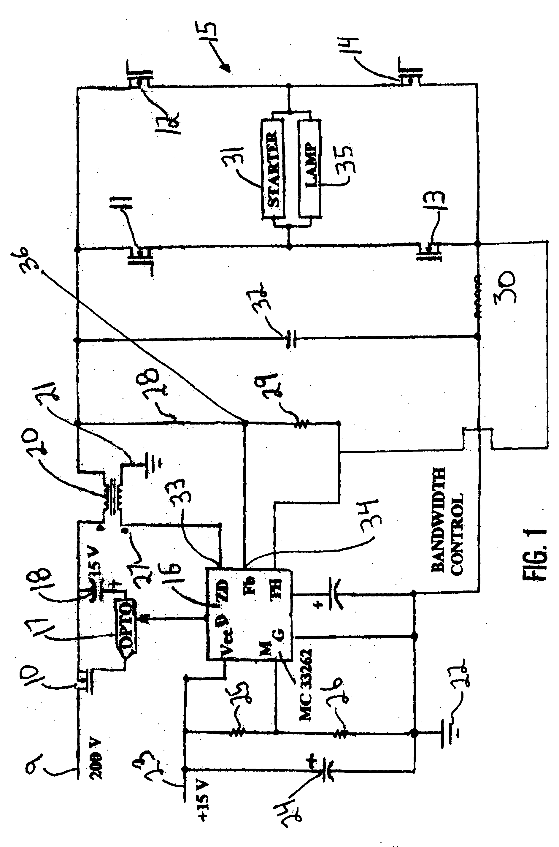
[0050] In this Example 1 sense resistor (30) is 1 ohm; voltage divider (36) (resistors 28:29) across capacitor (32) has a ratio of 100:1, the voltage across capacitor (32) is 100 volts because a 150 Watt lamp typically operates at 100 volts. I Lamp (lamp current) is 1.5 amps, and V-R sense (voltage across sense resistor (30)) is 100 divided by 1 (ratio of voltage divider) is Vd 1 volt. Vd (1 volt) plus I Lamp (1.5) totals to 2.5 volts, which is set as to equal the internal reference voltage (2.5 volts) of IC (16). In other words, the voltage divider ratio is selected by the circuit designer, so that at proper operation, the composite feedback signal to Fb equals the reference voltage of IC (16).
example 2
[0051] The lamp is an aged S-56 HPS lamp in which the electrodes are worn. The V Lamp is 150 volts, much higher than in Example 1 above. Vc across capacitor (32) is 150 volts; V-R sense (across sense resistor (30)) is therefore adjusted by the feedback to be 1 volt (I Lamp=1 amp) so that f.b=1.5+1=2.5V. The lamp is operated at 150 volts and 1 amp to provide 150 Watts of power consumption.
example 3
[0052] The lamp is a S-55 lamp which by error replaces a S-56 lamp. The S-55 has a nominal 55-volt operating voltage but would likely operate at about 60 volts because of reduced beam current with the above-described ballast of FIG. 1. In this Example Vd=0.6 volts (60 / 100); I-R sense is adjusted by the feedback loop (Fb) to 1.9 amps, i.e., 0.6+1.9=2.5V. The voltage at R sense resistor (30) (1.9 volts) plus Vd (at tap of voltage divider (36)) at 0.6 volts gives a total feedback voltage Fb of 2.5 volts, which equals the reference voltage of IC (16). In this Example the power is 60 volts×1.9 amps or 114 Watts, which is a reduced power consumption. The lamp would still operate although with a reduced light output, even under totally abnormal conditions.
[0053] Although the examples above utilize HPS bulbs, the ballast of the present may be useful in controlling and regulating other fluctuating and / or non-linear loads, such as certain motors, HID lamps (not only HPS lamps), arrays of LED...
PUM
 Abstract
Description
Claims
Application Information