High frequency reaction processing system

a processing system and high frequency technology, applied in the direction of waveguides, electric/magnetic/electromagnetic heating, electrical equipment, etc., can solve the problems of impracticality in use, large electric power in a single waveguide of an apparatus, etc., and achieve the effect of large area, durable circuit structure and increased area

Inactive Publication Date: 2005-09-29
TAKAMATSU TOSHIYUKI
View PDF13 Cites 241 Cited by
  • Summary
  • Abstract
  • Description
  • Claims
  • Application Information

AI Technical Summary

Benefits of technology

[0035] Moreover, if the high frequency reaction processing system is a plasma generating system, an electron density of the ionized gas plasma in the inner container increases with the supplied electric power increasing and the character of a border plane of ionized gas plasma becomes close to the one of conductor. Then, the electromagnetic wave reflected in the region which is closed with looped infinitely long dielectric transmission surface and the border plane of the ionized gas plasma. Thus, the invention enables to increase the area, in which the electromagnetic wave travels and generate electric field over a large area.
[0036] It is necessary to bias a voltage high enough to separate ionized gas to the termination of the circuit in order to generate plasma from non-plasma state in the plasma load portion. As a result of adopting the structure stated above, a resonance circuit is formed. A high voltage is generated and it is becomes easy to trigger plasma generation on the side of the termination. Moreover, a stable circuit is able to be formed, since the high frequency wave coupling portion and dielectric transmission surface are formed as equivalent as a circuit-type matching device and the load circuit is separated away from the oscillating portion. Consequently, the structure of the circuit is durable against reflected waves returning to the oscillator and able to increase electric power supplied to the load.

Problems solved by technology

Some prior high frequency reaction processing systems are high-powered by connecting loads to microwave 3D circuits with plural oscillators, because a power of a magnetron oscillator is limited for a microwave band.
It is possible to supply much electric power in a single waveguide of an apparatus but impractical in use because a high power magnetron or a special power supply necessary for the apparatus is hardly available in market.

Method used


Image

  • High frequency reaction processing system
  • High frequency reaction processing system
  • High frequency reaction processing system

Examples


first embodiment

[0153] The high frequency reaction processing system, a plasma generating system of the first embodiment, is explained below according to the figures.

[0154] In the system, the cylindrical or spherical dielectric transmission surface is composed. The high frequency wave coupling portion is located on the cylindrical or spherical plane in order to make the dielectric transmission surface equivalent to an infinitely long line. A length of the looped line is at least integer times ¼ of the wavelength of the guided high frequency wave. Moreover, the outside region of the container, which is the infinitely long dielectric transmission surface, except the high frequency wave coupling portion is covered with a conductive material. The discharged gas plasma vacuum container is composed of dielectric material and is also a vacuum container, which has, at least, a portion of the face ¼ of the wavelength of the guided high frequency wave away from the border plane between the conductive plane a...

second embodiment

[0235] As a specific example of the second embodiment, the fourth to the sixth examples and modifications of them are explained below.

[0236]FIG. 53 shows a vertical sectional view and a horizontal sectional view on y1-y2 of a microwave reaction processing portion in the fourth example of the present invention.

[0237] Shown in FIG. 53, the high frequency waves “247” are oscillated from two microwave oscillators and respectively guided through waveguides “244” into a reaction processing portion of the system of the present invention. The processing container is composed of a cylindrical quartz tube “255” as the dielectric inner container Vbn “241” and an aluminum door sample stage “257” and sealed with an O-ring “258”. One or more gas exhausting port “261” is located on a container wall “259”, if the process needs gas exhausting. The gas exhausting port can be the gas leading port according to the process.

[0238] In the processing system, a solid object “213”, which is not conductive,...

third embodiment

[0273] The high frequency reaction processing system of the third embodiment as a ultraviolet ray excitation processing system is explained below according to the figures.

[0274]FIG. 62 shows a schematic diagram of the structure of the microwave reaction processing system with members for high frequency wave transmission system.

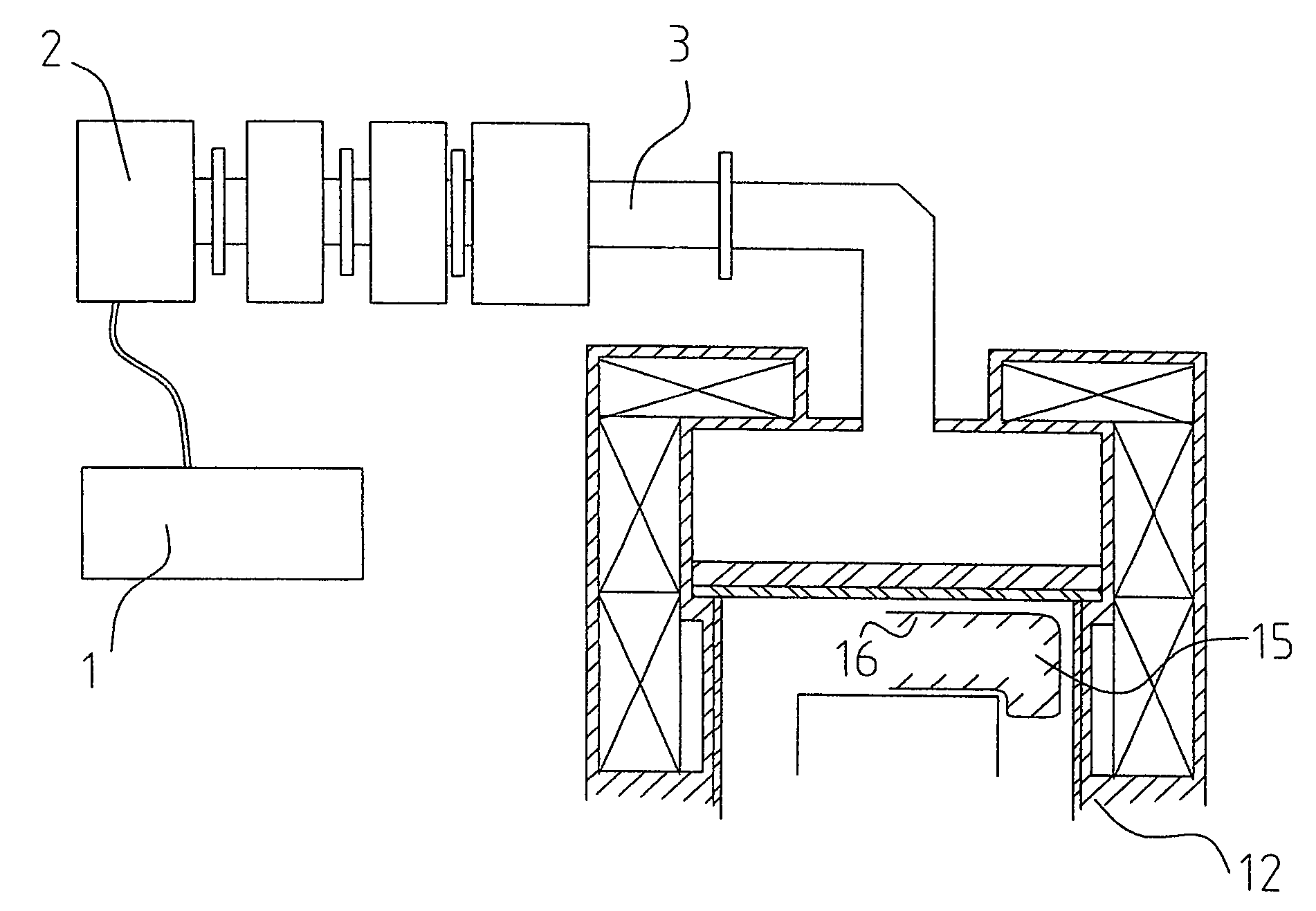
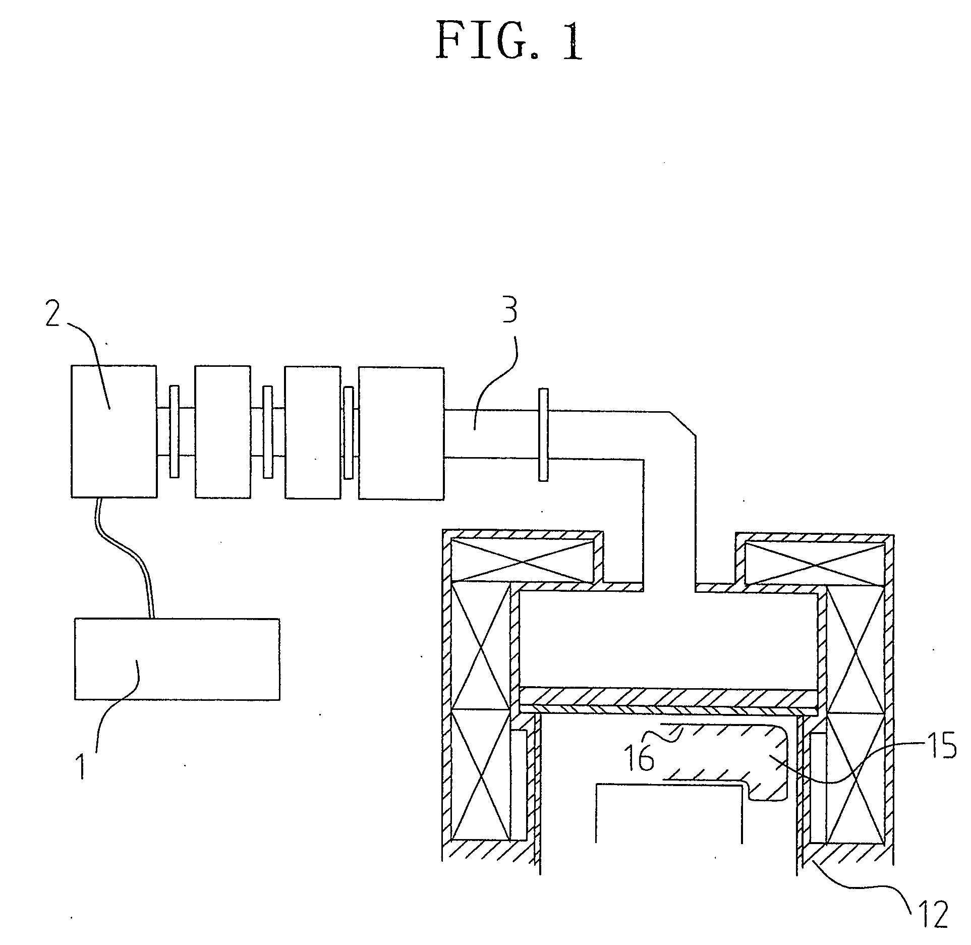
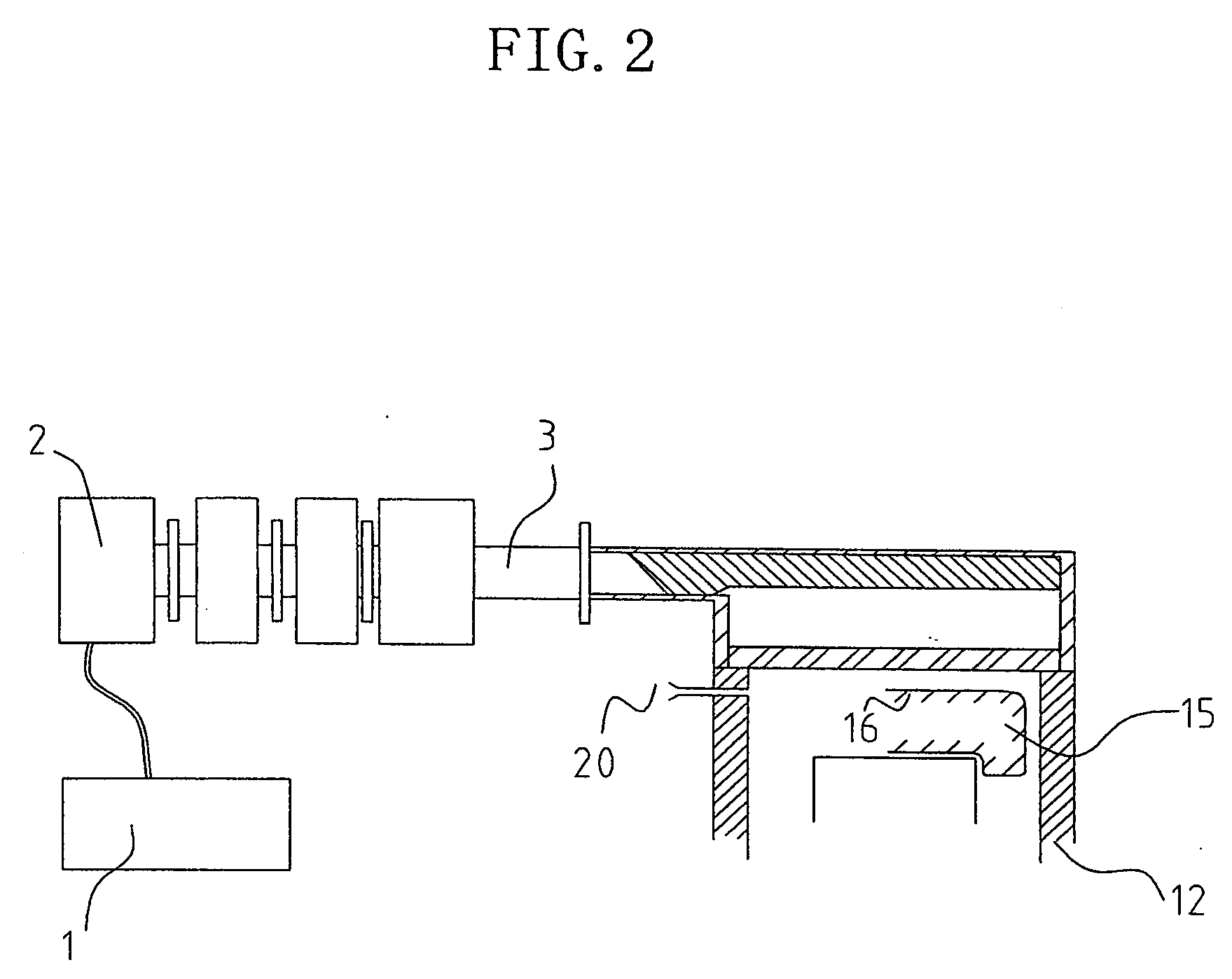
[0275] A high frequency oscillator “305” includes a magnetron and oscillates high frequency waves by electric power with a high voltage from a microwave power supply “306”. The electromagnetic wave travels through a waveguide “303” and is guided to a dielectric outer container Va “340”, a dielectric transmission surface, at the high frequency wave coupling portion. The outer side face of the outer container Va except the high frequency wave coupling portion is covered with the conductive material, which has the ground potential same as the waveguide. Thus, the guided electromagnetic waves spread and travel along the side face of the outer container Va “340”, ...


PUM


Abstract

A high frequency reaction processing system comprising an outer container (40) made of a dielictric material and having two end faces, which can close the inner cavity, one or more high frequency wave coupling portion (42) disposed at arbitrary position on the outer surface of the outer container (40), one or more inner container (41) made of a dielectric material and having two end faces, which can closeg the inner cavity, disposed at a position for receiving a high frequency wave guided through the high frequency wave coupling portion (42) without touching the inner side face of the outer container (40), and a covering portion (43) made of a conductive material, for covering the outer surface of the outer container except for the area occupied with the high frequency wave coupling portion (42) and sustaining the potential at a level equal to the ground potential of a waveguide line.

Description

FIELD OF THE INVENTION [0001] This invention relates to a high frequency reaction processing system for efficiently guiding high power and high frequency wave into a load with large capacity without generating many reflected waves in a processing region, and reaction processing of an object by high frequency wave. BACKGROUND ART [0002] In prior arts of high frequency reaction processing systems, an end face of a high frequency wave termination load forms an end face of a cavity-resonance waveguide. A section of the load perpendicular to the load functions as an end of a high frequency wave. [0003] For example, in an apparatus stated in Japanese Non-examined Publication 8-236298, a disk-shaped member transmissive for a high frequency wave is located in a cylindrical container made of conductive material on the waveguide-side of a plane perpendicular to the axis of the tube at the position approximately n / 2 times of a wavelength of a guided high frequency wave away from the waveguide-...

Claims


Application Information

Patent Timeline
Patent Type & Authority Applications(United States)
IPC IPC(8): H01P1/20H01P3/12H05B6/64H05B6/80
CPCH05B6/806H05B6/70
Inventor TAKAMATSU, TOSHIYUKI
Owner TAKAMATSU TOSHIYUKI
Why Eureka
Try Eureka