
Multidimensional pump apparatus and method for fully automated complex mixtures separation, identification, and quantification

Inactive Publication Date: 2005-09-29
YANG FR JIANN FU
View PDF0 Cites 35 Cited by
  • Summary
  • Abstract
  • Description
  • Claims
  • Application Information

AI Technical Summary

Benefits of technology

[0009] In the above step one; a high-pressure injection valve can be used to inject sample. The cleavage reagents A and B in the step 8 can also be pumped by two syringe pumps into a micro-mixer and then to the cleavage column(s). A multi-channel selection valve 8 (e.g. Valco 24 port multichannel selection valve) can be utilized to reduce the total analysis time of a complex sample. The apparatus includes the “multi-channel selection valve” as shown in FIG. 12 to collect multiple fractions of eluted sample component from the Biotin affinity column into multiple arrays of cleavage columns or micro-plates.

Problems solved by technology

Unfortunately, such split flow techniques are not reliable for routine applications at nano-flow rates as the flow restriction through the capillary column could change due to column inlet port blockage or flow restriction change inside the flow splitter.
It is particularly difficult to maintain a constant split ratio when a high split ratio (for example 500 μl / min to 0.1 μl / min split i.e. 5000 to 1 split ratio) is required for nano-flow rate applications.
However, the 2-D gel electrophoresis method is difficult to automate and cannot detect low abundance proteins.
It cannot be practiced with small quantity of samples and is not automated.
As a result, the method was not easily applicable to routine low abundance cellular proteins separation, identification, and quantification.

Method used


Image

  • Multidimensional pump apparatus and method for fully automated complex mixtures separation, identification, and quantification
  • Multidimensional pump apparatus and method for fully automated complex mixtures separation, identification, and quantification
  • Multidimensional pump apparatus and method for fully automated complex mixtures separation, identification, and quantification

Examples


Embodiment Construction

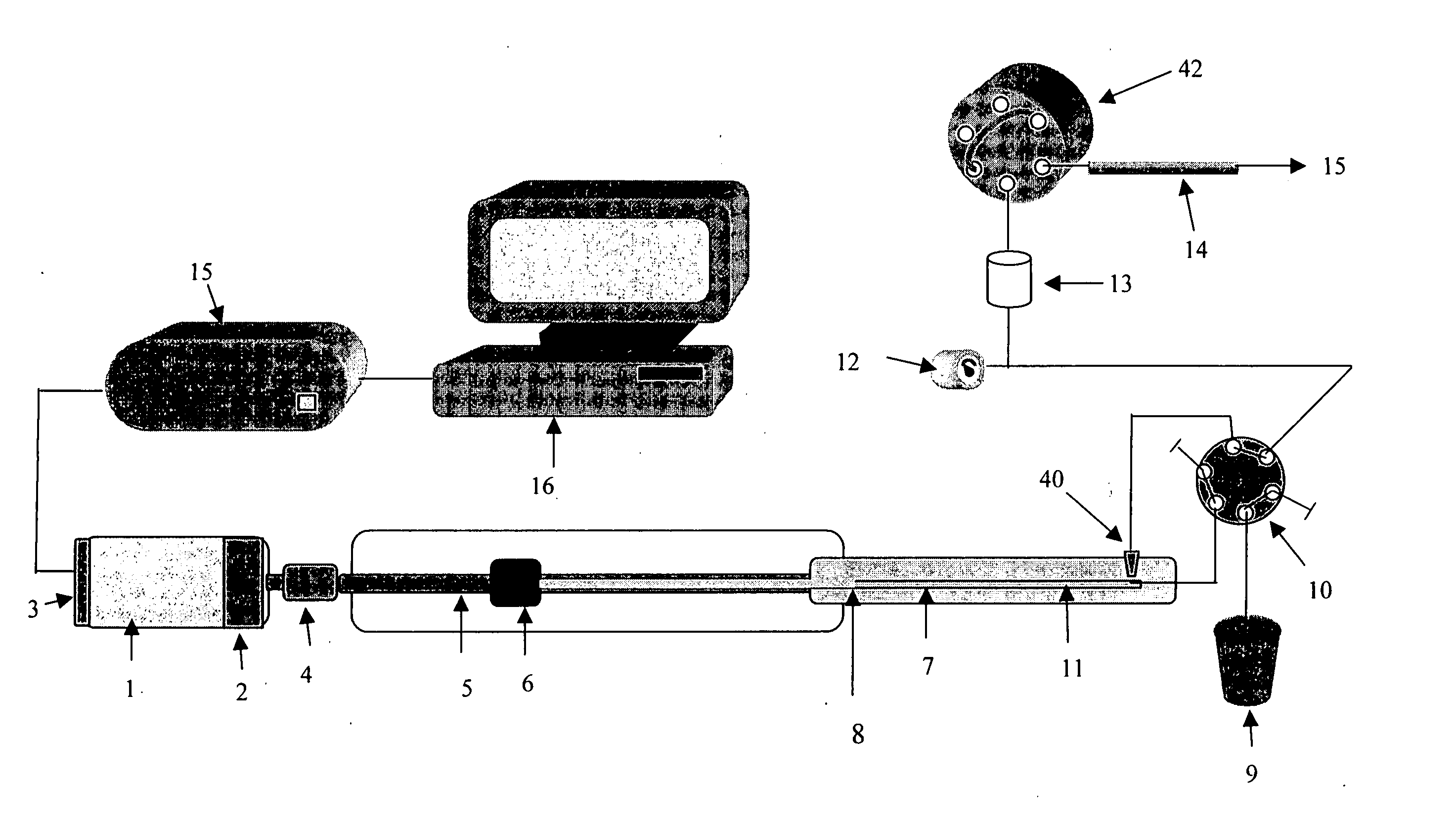
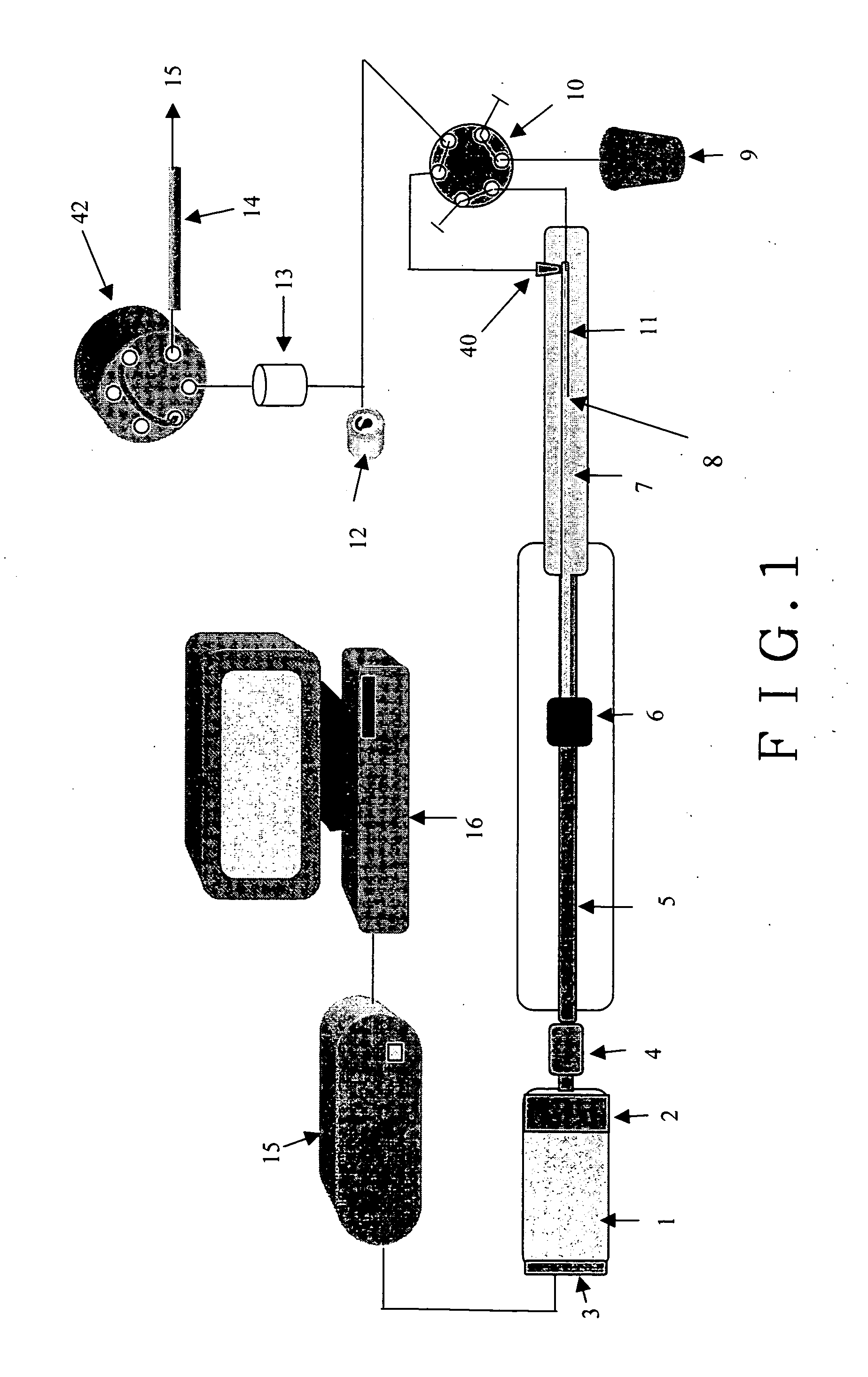
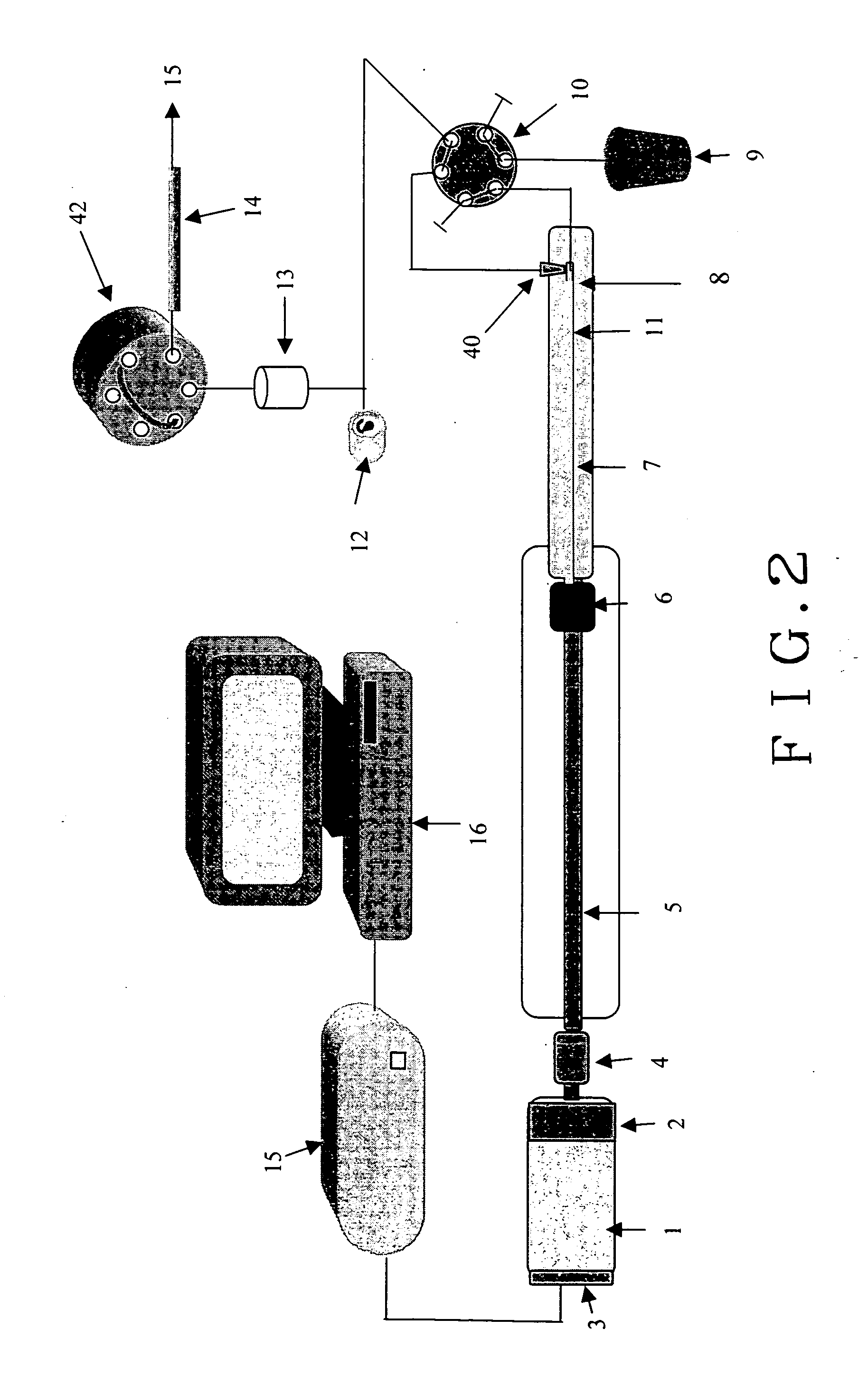
[0027]FIG. 1 is a simplified block diagram depicting key components of a preferred embodiment of a pumping system having a Servomotor 1 (or a step motor) with a gear box 2 of 50 to 1 ratio that has an optical encoder 3 mounted on the motor shaft for closed loop digital control for a motor 1. The motor 1 can be controlled to have one revolution in 40 to 80 minutes or longer. A total of 14,336,000 digital count is required to move the piston 7 linearly for 7 cm. The piston 7 is a 0,159 cm diameter zirconium oxide that has piston volume of 150 μl. The motion of the piston 7 is controlled by proportion, integration and differentiation (PID) algorithm to ensure reproducible 0.5 nl / digital count closed loop control. At 40 minutes per revolution or 1 mm travel length, the minimum flow rate can be deliver with the servo motor 1 alone is 50 nl / min. The preferred embodiment of the invention having also a gear box 2 of 50 to 1 speed reduction factor to further increase the control accuracy to ...


PUM


Abstract

A fluid pumping system can be operated in dual control modes: as a syringe pump for nano-flow solvent delivery; and as a reciprocating pump for micro- and analytical flow solvent delivery. The fluid pumping system is also operated in a closed-loop digital control process using an optical encoder for piston refill stroke begin and end synchronization with a switching valve On and Off. A multidimensional apparatus and procedure using up to 8 of the invented fluid pumps for a fully automated procedure such as ICA™ chemistry for cellular protein separation, identification and quantification.

Description

BACKGROUND OF THE INVENTION [0001] 1. Field: [0002] The invention relates to high-pressure fluid pumping system that is capable of fluid delivery from nano- to analytical flow rates and more particularly to multidimensional HPLC instrumentation and method for the separation, identification, and quantification of complex mixtures such as cellular proteins and carbohydrates. [0003] 2. State of the Art: [0004] Fluid pumping systems for high-pressure liquid chromatography (referred to hereinafter as HPLC) and the like are well know. In HPLC, complex sample with multiple components is transported through a column packed with particles of designed selectivity to cause separation of the components of the mixture when mobile solvent that is pumped through the column transports them. Typical prior art pumps employed in these applications were exemplified in U.S. Pat. No. 4,045,343 to Achener et al, U.S. Pat. No. 4,260,342 to Leka et al, U.S. Pat. No. 3,599,045 to Gordon et al, and U.S. Pat. ...

Claims


Application Information

Patent Timeline
IPC IPC(8): B01L3/02F04B7/00F04B7/02F04B9/02F04B13/00F04B13/02F04B17/00F04B49/00G01N30/36
CPCB01L3/0227F04B7/0076F04B7/02F04B9/02G01N30/36F04B13/02F04B2201/0201F04B2201/0206F04B13/00
Inventor YANG, FRANK JIANN-FU
Owner YANG FR JIANN FU
Learn More