Thrust, with or without the ejection of propellant

Inactive Publication Date: 2005-10-06
WILLETT EVERETT WADE
View PDF23 Cites 2 Cited by
  • Summary
  • Abstract
  • Description
  • Claims
  • Application Information

AI Technical Summary

Benefits of technology

[0013] The primary objective of the present invention is to significantly reduce the fuel consumption of propellant producing engines and possible proposed propellant producing engines. The present invention relates to a vehicle for marine usage, (surface or underwater) outer space or in the atmosphere of the earth. The present invention avoids the drawbacks of prior art which consumes vast quantities of fuel. Within the present invention extreme propellant mass and extreme propellant pressure are contained and stabilized between the levitating mass, the hollow passage-way, the engine and engine parts. The propellant producing engine is throttled back at this time to approximately ten to twenty percent of the engines capabilities, thus decreasing the rate of fuel consumption. The propellant producing engine is throttled forward as need be, maintaining a constant extreme pressure of propellant and propellant mass, thus providing an efficient means of fuel consumption. Another objective of the present invention is to significantly reduce the decibel levels produced by current propellant producing engines and possibly proposed propellant producing engines.
[0014] In carrying out the present invention propellant is trapped between the levitating mass, the engine nacelle or (hallow passage-way) and the propellant producing engine and engine parts. As a consequence, little or no propellant escapes from the vehicle's structure. Thus the audio signature or decibel levels of the propellant producing engine are drastically reduced. A further objective of the present invention is to deplete the expulsion of harmful exhaust gasses and by-products produced by current propellant producing engines or possibly proposed propellant producing engines, which gradually destroy the ozone layer. In accordance with the present invention, propellant is prevented from escaping the vehicle's structure and is trapped between the hallow passageway, propellant producing engines and levitating mass, thus decreasing the amount of harmful exhaust gasses released into the surrounding medium. Still another objective of the present invention is to significantly reduce the downdraft of air when the present invention's configuration corresponds to a helicopter or vehicle's with vertical takeoff or landing (VTOL) characteristics. This will be appreciated when the balanced arrangement of levitated masses are placed within the vehicle's structure at calculated vertical axis which traps extreme propellant pressure and extreme propellant mass between it and the hallow passage-ways, the propellant producing engine and engine parts, thus little or no downdraft of propellant escapes from the vehicle.
[0015] Another aspect of the present invention is to significantly reduce the harmful conditions of exhaust blast to humans, created by current propellant producing engines or possible proposed propellant producing engines. Exploiting the present inventions distinctive traits, preventing escape of produced propellant, with the placement of the levitating mass toward the end of the propellant producing engines, nacelle, or hollow passageway, little or no exhaust blast is created.
[0016] A further aspect of the current invention contributes into calculating proposed or existing commercial, private or military airports landmasses. These new innovative decisions would greatly reduce the area of land mass needed, currently imposed by today's airports external form. This again will be appreciated when the levitating mass of the present invention traps extreme propellant mass and extreme propellant pressure between the balance arrangement of vertical axis within the vehicle's structure, thus the vehicle's transition from a static position to a forward motion or perpendicular angles of movement.
[0018] It is a further object of the invention to provide a levitating mass for imparting momentum to a vehicle by trapping propellant, which increases propellant pressure, thus transmitting in predetermined directions massive quantities of force.

Problems solved by technology

Unfortunately rocket engines consume huge quantities of propellant that must be stored on board the vehicle.
For example U.S. Pat. No 5,211,006 discloses a magneto-hydrodynamic propulsion system that is believed to be theoretically operative but is not a practical system because the system is environmentally disadvantageous because, it employs magnetic fields pulsating into the internal atmosphere, within the vehicle.
These prior art disclosures exist in theory mathematical computation and scale models, and to date have no practical use.

Method used


Image

  • Thrust, with or without the ejection of propellant
  • Thrust, with or without the ejection of propellant
  • Thrust, with or without the ejection of propellant

Examples


Embodiment Construction

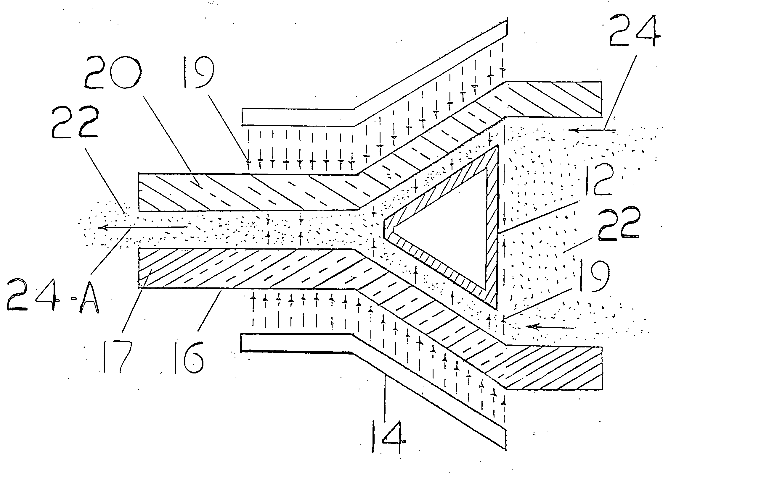
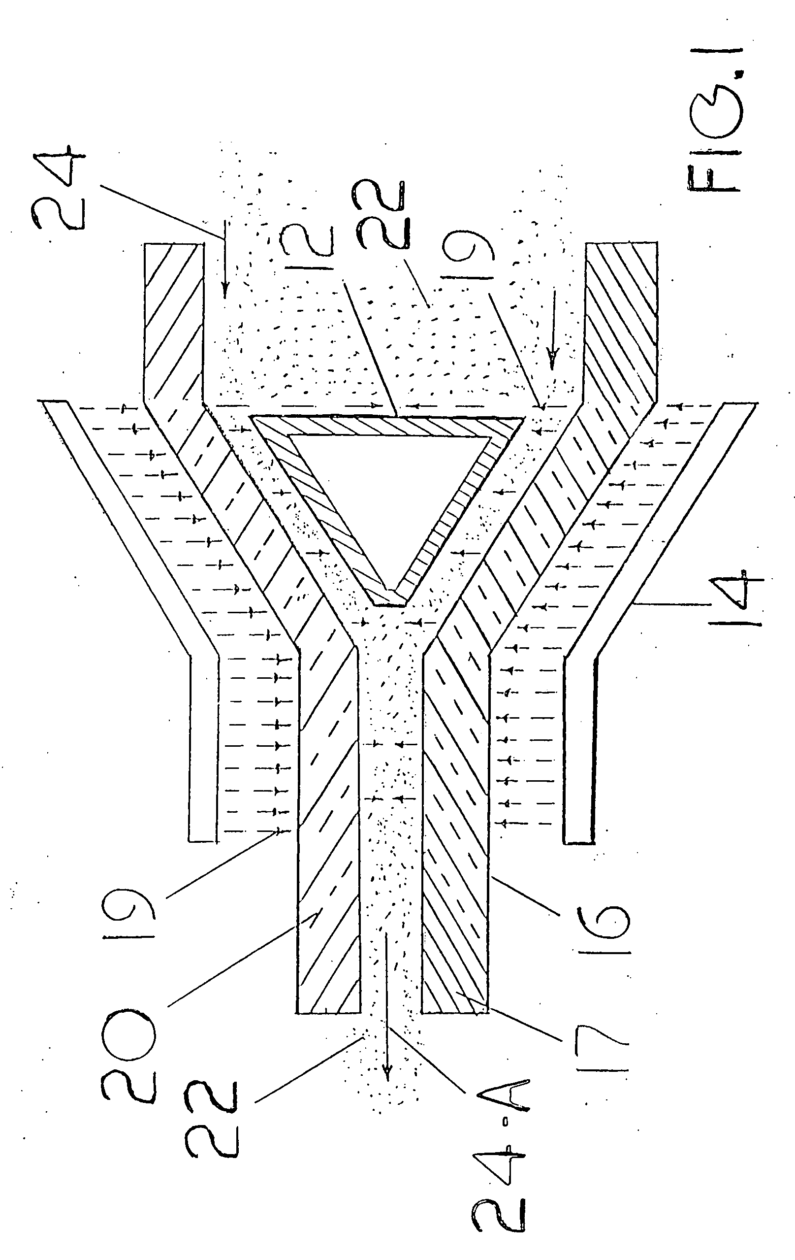
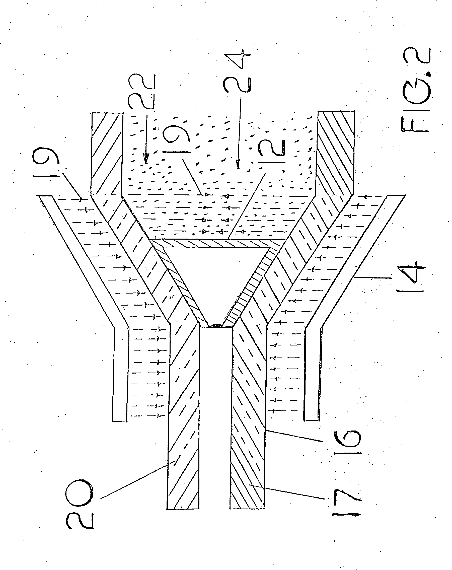
[0037]FIG. 1 is merely illustrative, as there are numerous variations and modifications, which may be made throughout the description. FIG. 1 is a basic example, partial cross sectional view of a levitating mass 12. The levitating mass 12 could be, but not necessarily designed in a circular configuration. The levitating mass or levitating masses 12 reside within the hollow passage-way 16 or hollow passage-ways 16 at predetermined locations to gain the most favorable results in affecting the vehicle's transition. The levitating mass 12 or levitating masses 12 comprise the composition 12-B repulsive to the maximum and minimum thermal range of accumulated propellant 22 pressure trapped between it, the hollow passage-way 16 and the propellant producing engine 27FIG. 4. The levitating mass 12 or levitating masses 12 also comprise the composition 12-B to oppose the maximum propulsive pressure of the accumulated propellant 22 trapped between the hollow passageway 16 and the propellant prod...


PUM


Abstract

Thrust, with or without the ejection of propellant in a vehicle by an arrangement of levitating masses or a levitating mass and operating method are provided for achieving economical fuel consumption. The invention comprises a method of producing forward thrust, aft thrust, a hovering position, control around the yaw, roll, and pitch axis by an arrangement of levitating masses or a levitating mass within the vehicles structure. The produced propellant may be manufactured from existing. technology such as a marine jet engine, jet engine, turbo fan engine, a solid propellant engine or a liquid propellant engine. The propellant may also be produced by proposed propulsion systems such as, an electric ion engine, a nuclear fission engine, a plasma fusion engine, a photon engine or an anti-matter engine. The levitation system can be designed from existing technology such as an electromagnet apparatus, a super conducting magnetic apparatus or the levitating mass can be completely self supported, that is, the repelling force that holds the levitating mass within a stationary position comes from within the levitating mass. The reaction of accumulated propellant pressure trapped between the levitating mass, the hollow passage-way, the propellant gate and the propellant producing engine exert a repelling force against the vehicle's structure, thus propelling the engine and the vehicle in which it is mounted.

Description

CROSS-REFERENCE TO RELATED APPLICATION [0001] This application claims the benefit of the provisional patent application # 60 / 510,600 file date Oct. 10, 2003FEDERALLY SOPONSORED REASEARCH [0002] Not Applicable BACKGROUND OF THE INVENTION [0003] 1. Field of the Invention [0004] The present invention relates to thrust, with or without the ejection of propellant by an arrangement of levitating masses, or a levitation mass, and methods for the production of such levitating masses, and for controlling such levitating masses for propelling a vehicle. [0005] 2. Prior Art [0006] Aerospace propulsion technology to date has rested firmly on the applications of the reaction principal, creating motion by expelling propellant mass from a vehicle. In present day vehicle propulsion systems the use of expelled propellant by a engine to produce a large amount of thrust necessarily to facilitate the transition of a vehicle is known. The term“thrust” is defined to mean the amount of propulsive force de...

Claims


Application Information

Patent Timeline
IPC IPC(8): F02K1/00F02K1/38F03H99/00
CPCF02K1/00F02K1/386F05D2260/96Y02T50/671F03H99/00Y02T50/60
Inventor WILLETT, EVERETT WADE
Owner WILLETT EVERETT WADE
Why Eureka
Try Eureka