

Carbon sequestration and dry reforming process and catalysts to produce same
- Summary
- Abstract
- Description
- Claims
- Application Information
AI Technical Summary
Benefits of technology
Problems solved by technology
Method used
Image

Examples
example 1
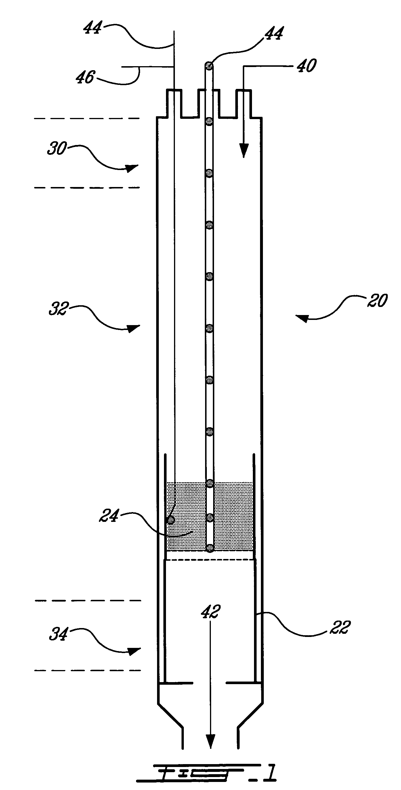
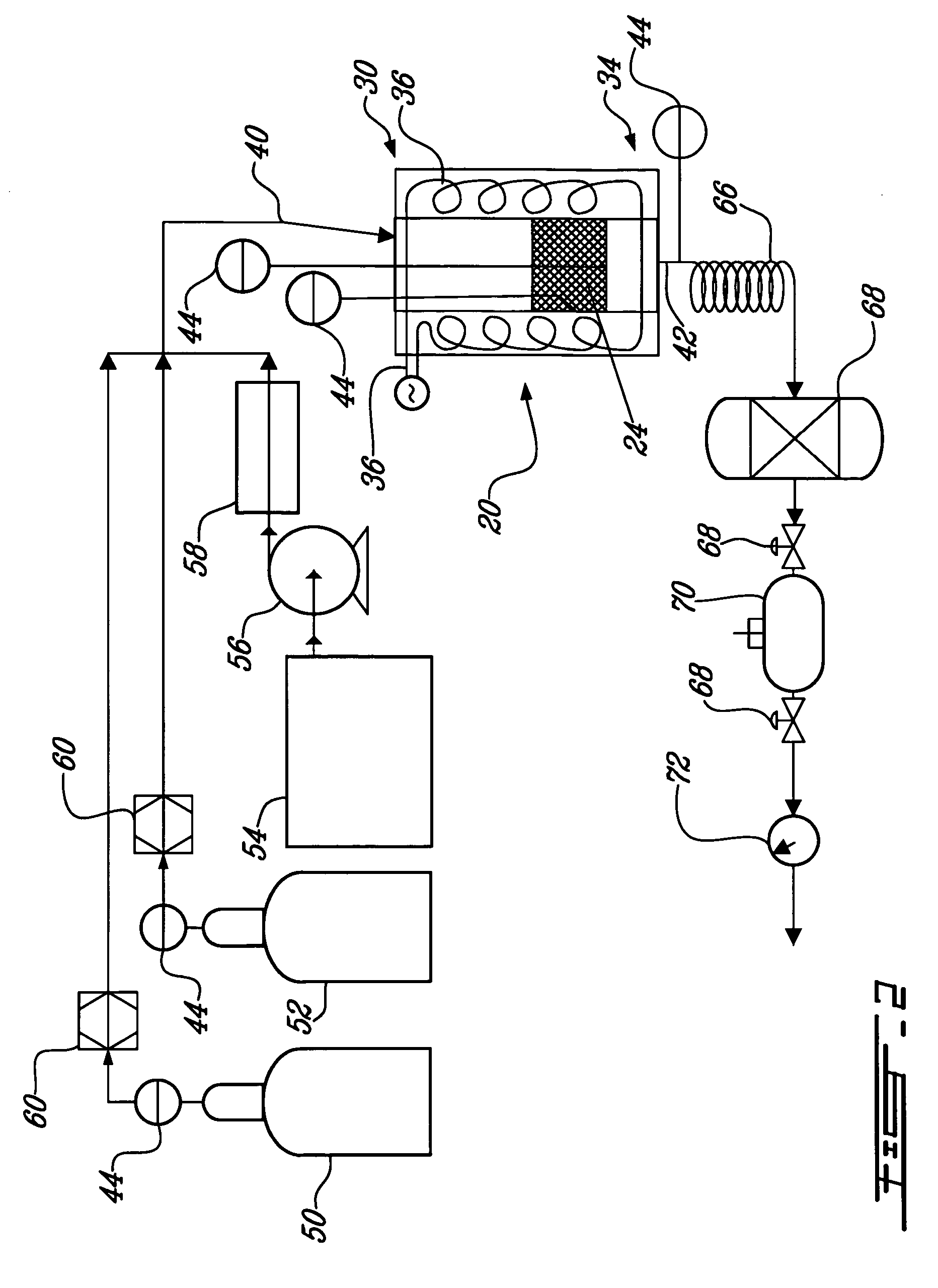
[0083] The first example refers to FIG. 2, which is a schematic flow sheet of the carbon sequestration and dry reforming process, at a laboratory scale, wherein either a gaseous or a liquid organic material is dry reformed. The process includes a source of carbon dioxide 50 in gaseous state, a source of an organic material in gaseous state 52, and / or a source of an organic material in liquid state 54. If dry reformed, the organic material in liquid state 54 at ambient temperature is pumped with a pump 56 to a preheater 58. The preheater 58 heats the organic material in liquid state 54 until it volatilizes. Mass flow meters 60 can be positioned on the gas lines to measure on line the reactant masses. The carbon dioxide 50 and at least one of the organic material in gaseous state 52 and the organic material in liquid state 54, now in gaseous state, form the reactant gas mixture 40. The reactant gas mixture 40 enters the upper portion 30 of the reactor 20 and is heated while moving dow...
example 2
[0084] The following example relates to the dry reforming of ethanol in the presence of ruthenium-promoted nickel on an alumina based support catalyst (NiRu / Al2O3 catalyst). Equation (3) (referred to above) is the dry reforming reaction.
[0085] Preparation of the Catalyst
[0086] The catalyst was prepared by co-impregnation of the support, which in the example was alumina, with RuCl3 and Ni(NO3)2, 6H2O precursors. An appropriate amount of the metal salts in an aqueous solution was added to the support (8 grams of Al2O3, 0.3238 gram of RuCl3, 3.17 grams of Ni(NO3)2, 6H2O). After a stirring maintained during 24 hours, the solid was placed in an oven for 12 hours at 80° C. The catalyst was then calcinated with air at 400° C. for 5 hours with a temperature ramp of 3° C. / minute.
[0087] Before initiating the experiment, the catalyst was reduced in situ under a hydrogen flow (150 ml / min) during 90 minutes at 400° C. The temperature was increased to the reaction temperature under nitrogen.
[...
example 3
[0093] The following example concerns the preparation of a 2D catalyst by the induction plasma technology.
[0094] The induction plasma technology has been used widely in the past to process materials. The ‘as-sprayed’ catalysts are produced using the suspension plasma spraying (SPS) concept (U.S. Pat. No. 5,609,921) applied to catalyst synthesis. Various approaches can be used in order to synthesize the catalyst. For instance Thermal Plasma Chemical Vapor Deposition (TPCVD) can be used by injecting nitrates for instance in the plasma discharge, as described in U.S. Pat. No. 5,032,568. However not every materials can be dissolved and the deposition rate in the vapor phase can be low. Working with saturated solutions such as suspensions can directly give a coating formed through the impingement of liquid droplets which are above the melting point of the catalysts and which can preserve some nanostructure because of the fast quench rate which can be imposed.
[0095] TPCVD was performed ...
PUM
| Property | Measurement | Unit |
|---|---|---|
| Temperature | aaaaa | aaaaa |
| Temperature | aaaaa | aaaaa |
| Volume | aaaaa | aaaaa |
Abstract
Description
Claims
Application Information