Organic electroluminescent device with chromophore dopants
- Summary
- Abstract
- Description
- Claims
- Application Information
AI Technical Summary
Benefits of technology
Problems solved by technology
Method used
Image

Examples
example 1
[0102] An organic electroluminescent device was prepared in the way described in what follows.
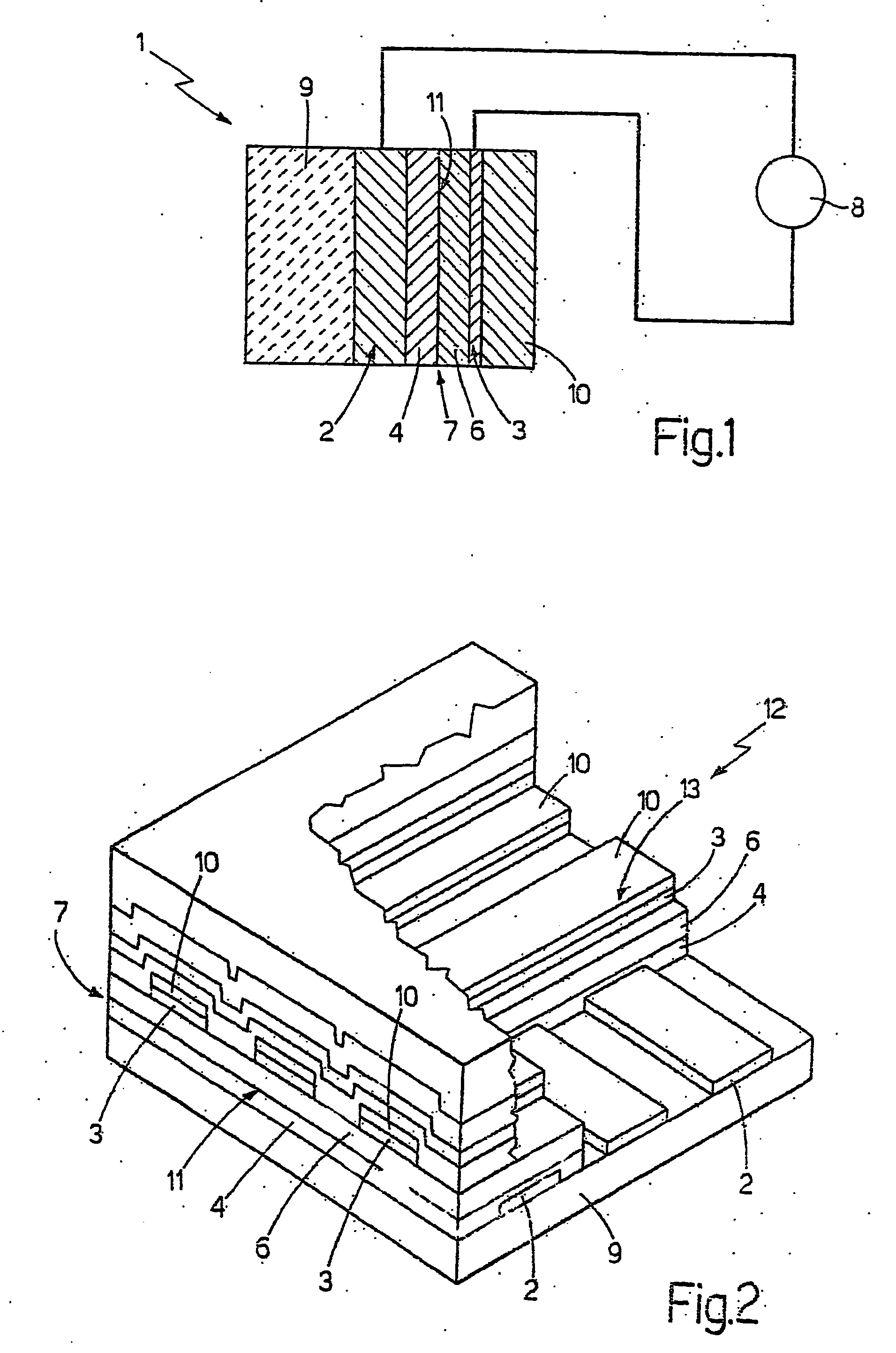
[0103] A plate of glass coated with a layer of indium and tin oxide, which had a thickness of approximately 100 nm and was substantially transparent, was cleaned by being dipped in a boiling solution of acetone and alcohol and by subsequently being put into an ultrasound washer for approximately thirty minutes.
[0104] At this point there was laid, using a spin coater, a first 60-nm thin film from a solution of 4,4′,4″-tris (N-3-methylphenyl-N-phenylamino)-triphenylamine (m-MTDATA): polycarbonate (PC): rubrene in the proportions 75:24:1 in dichloromethane. On top of this, by sublimation in a high-vacuum evaporator and at a pressure of 8×10⁻¹ Pa, there were deposited: a 60-nm layer of 2-(4-biphenyl)-5-phenyl-1,3,4-oxadiazole (PBD); a 25-nm layer of calcium; and a 100-nm layer of silver.
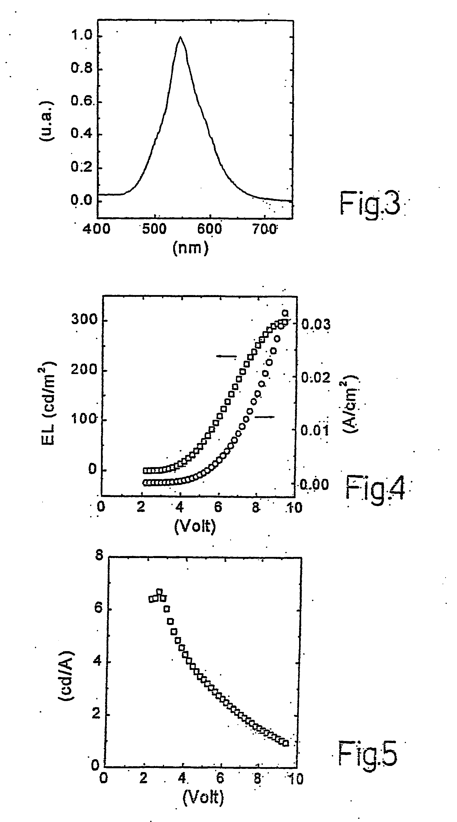
[0105] The device thus obtained, which had an active surface of 0.07 cm2, was tested under laboratory cond...
example 2
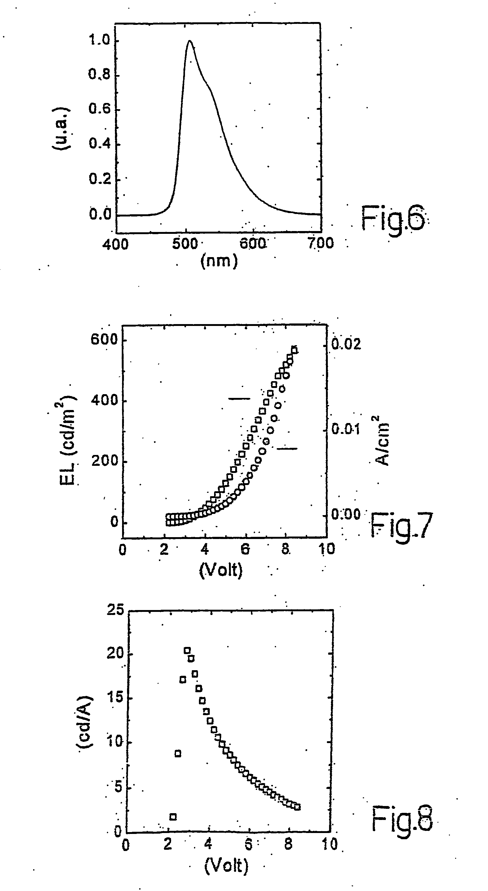
[0107] An organic electroluminescent device was prepared in a substantially identical way as the organic electroluminescent device of Example 1 except for the fact that, instead of the layer of m-MTDATA:PC:rubrene, there was deposited a layer of m-MTDATA:PC:Ir(ppy)3 in the proportions 75:20:5. Ir(ppy)3 is iridium tris (2-phenylpyridine).
[0108] The device thus obtained, which had an active surface of 0.07 cm2, was tested under laboratory conditions (i.e., with a temperature of between 20° C. and 24° C. and with a humidity of between 55% and 65%) and revealed an electromagnetic emission in the green having a spectrum, illustrated in FIG. 6, characteristic of Ir(ppy)3. The curves which were obtained experimentally from the use of said device and which represent the intensity of electroluminescence and the current density as a function of the applied voltage are illustrated in FIG. 7. The curve which was obtained experimentally from the use of said device and which represents the effic...
example 3
[0110] An organic electroluminescent device was prepared in a substantially identical way as the organic electroluminescent device of Example 1 except for the fact that, instead of the layer of m-MTDATA:PC:rubrene, there was deposited a layer of m-MTDATA:PC:Ir(ppy)3:rubrene in the proportions 73:20:6:1.
[0111] The device thus obtained, which had an active surface of 0.07 cm2, was tested under laboratory conditions (i.e., with a temperature of between 20° C. and 24° C. and with a humidity of between 55% and 65%) and revealed an electromagnetic emission in the green-yellow having a spectrum illustrated in FIG. 9. The curves which were obtained experimentally from the use of said device and which represent the intensity of electroluminescence and the current density as a function of the applied voltage are illustrated in FIG. 10. The curve, which was obtained experimentally from the use of said device and which represents the efficiency as a function of the applied voltage, is illustra...
PUM
| Property | Measurement | Unit |
|---|---|---|
| Energy | aaaaa | aaaaa |
| Ionization potential | aaaaa | aaaaa |
| Transparency | aaaaa | aaaaa |
Abstract
Description
Claims
Application Information
PatSnap Eureka turns technology decisions into work you can execute. Powered by our Innovation Knowledge Graph, it runs expert workflows across engineering, life sciences, materials and intellectual property. Get your review-ready output in minutes.


