
Hydrogen transport membranes for dehydrogenation reactions

a technology of transport membrane and dehydrogenation reaction, which is applied in the direction of hydrocarbon preparation catalyst, separation process, organic chemistry, etc., can solve the problems of poor conversion yield and selectivity, energy intensive, and limited equilibrium conversion thermodynamically, and achieve excellent selectivity and high yield

Inactive Publication Date: 2005-10-06
UCHICAGO ARGONNE LLC
View PDF10 Cites 4 Cited by
  • Summary
  • Abstract
  • Description
  • Claims
  • Application Information

AI Technical Summary

Benefits of technology

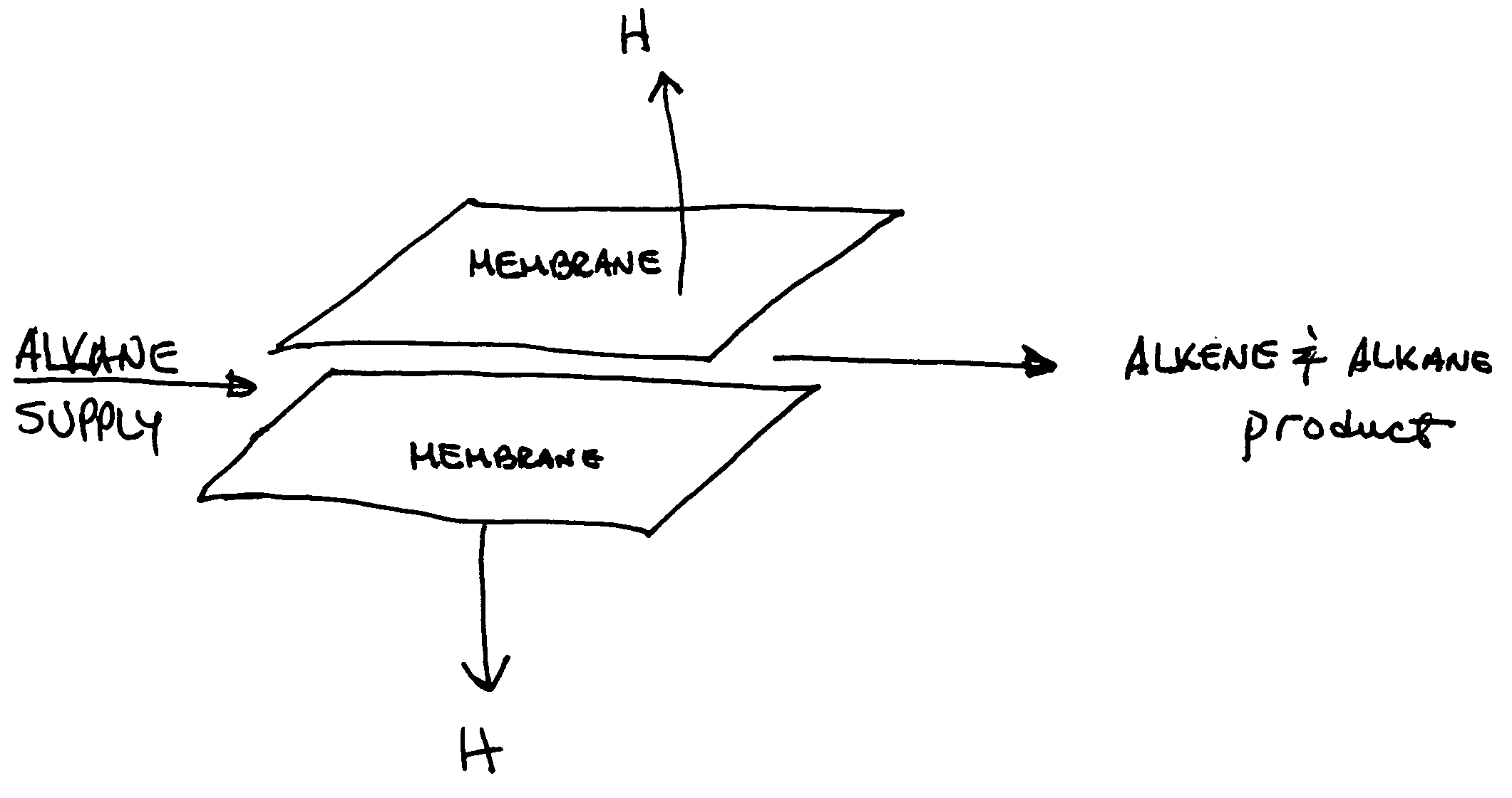
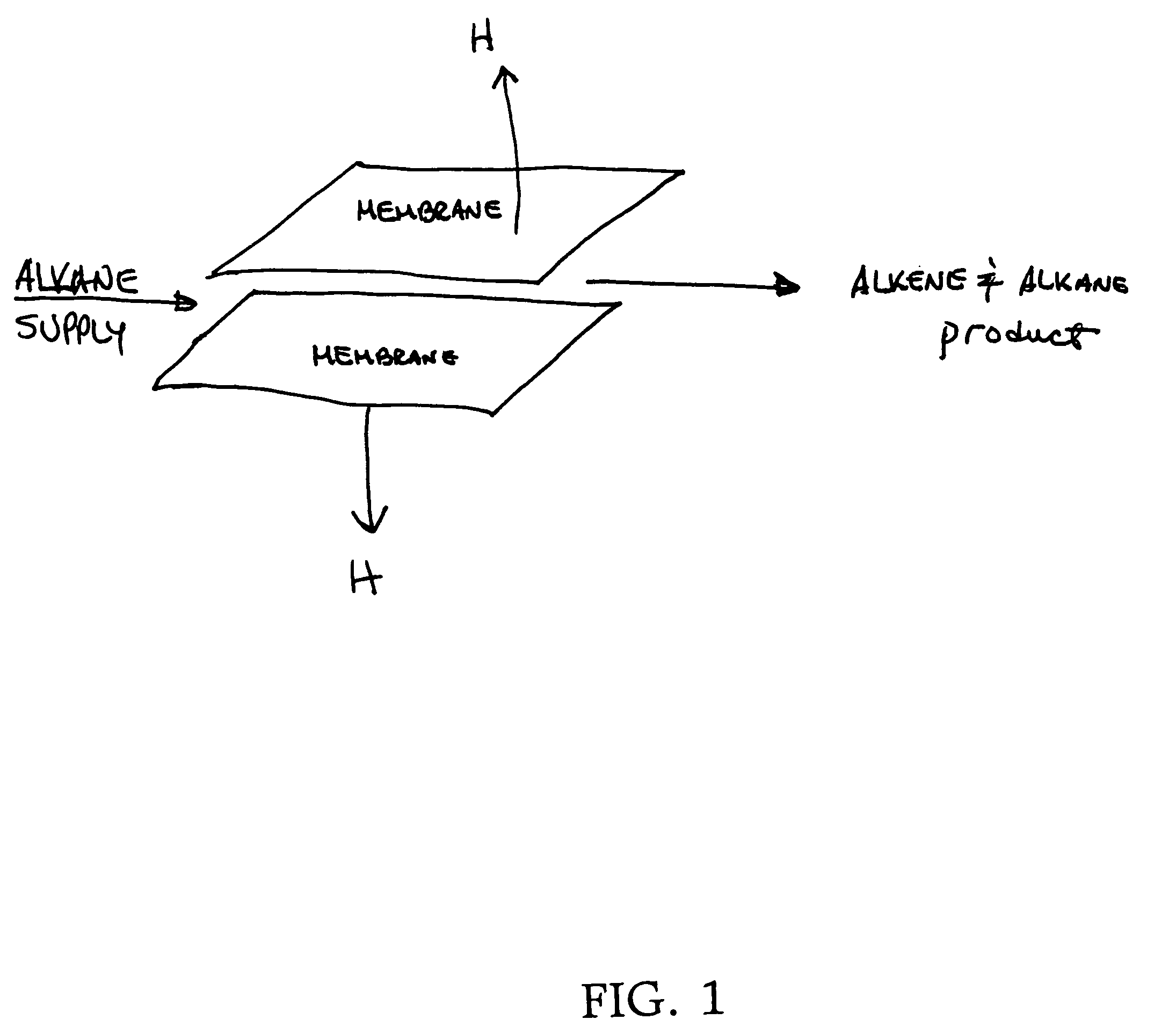
The present invention is about a method and apparatus for dehydrogenating hydrocarbons to produce high value-added chemicals and feed stocks. The invention uses hydrogen transport membranes to convert alkanes to olefins with a high yield and excellent selectivity. The invention can be used to convert C2 and / or higher alkanes to olefins by contacting them with a metal composite membrane and separating the formed olefins from the membrane while separating the hydrogen from the other side. The invention has certain novel features and advantages, such as the use of atomic hydrogen from the dehydrogenation of the alkanes, and the separation of the formed olefins from the membrane.

Problems solved by technology

In addition, the conversion yield and selectivity for both propylene and ethylene are poor using the current steam cracking procedure in addition to the following problems with large cracking plants.
Second, while there is some flexibility in the product output based on feed and operating conditions, this is rather limited and these units invariably produce one or more low value products(s) that the operators would rather not make.
Third, they operate at high temperatures (800 to 1200 degrees F.) and are very energy intensive.
Moreover, the thermal cracking reaction is highly endothermic (substantial energy input is required); the equilibrium conversion is thermodynamically limited and selectivity declines at higher temperatures; carbon oxide formation occurs; side reactions occur (undesired product formation) requiring extensive product purification.
While a number of schemes have been proposed to couple olefin formation with further down stream products to improve efficiencies, they have not found wide-spread commercial application.

Method used


Image

  • Hydrogen transport membranes for dehydrogenation reactions
  • Hydrogen transport membranes for dehydrogenation reactions

Examples


Embodiment Construction

[0014] This invention relates to membranes disclosed in U.S. Pat. No. 6,569,226 issued May 27, 2003, the entire disclosure of which is incorporated by reference. The membranes of the present invention may be in sheet form or tubular form or honeycomb form, the latter being illustrated in U.S. Pat. No. 5,356,728 issued Oct. 18, 1994, the entire disclosure of which is incorporated herein by reference. Membranes of the type disclosed in the '226 patent separate hydrogen from a feedstock containing hydrogen. However, it is has been discovered that when feedstocks contain alkanes, use of the membranes disclosed in the '226 patent remove hydrogen from the alkanes converting same to alkenes or olefins with very high activity and very high yield. While the membranes disclosed in the '226 patent are operable for the present invention, it has been found that certain of the membranes which pass or are permeable to atomic hydrogen rather than protons and which do not pass electrons are preferab...


PUM

PropertyMeasurementUnit
thicknessaaaaaaaaaa
thicknessaaaaaaaaaa
temperatureaaaaaaaaaa

Abstract

A method of converting C2 and / or higher alkanes to olefins by contacting a feedstock containing C2 and / or higher alkanes with a first surface of a metal composite membrane of a sintered homogenous mixture of an Al oxide or stabilized or partially stabilized Zr oxide ceramic powder and a metal powder of one or more of Pd, Nb, V, Zr, Ta and / or alloys or mixtures thereof. The alkanes dehydrogenate to olefins by contact with the first surface with substantially only atomic hydrogen from the dehydrogenation of the alkanes passing through the metal composite membrane. Apparatus for effecting the conversion and separation is also disclosed.

Description

[0001] The United States Government has rights in this invention pursuant to Contract No. W-31-109-ENG-38 between the U.S. Department of Energy (DOE) and The University of Chicago representing Argonne National Laboratory.BACKGROUND OF THE INVENTION [0002] Current olefin (ethylene, propylene, and 1,3-butadiene) are made by cracking hydrocarbon feeds ranging from LPG to light naphtha in very large thermal steam crackers. In addition, the conversion yield and selectivity for both propylene and ethylene are poor using the current steam cracking procedure in addition to the following problems with large cracking plants. [0003] There are three drawbacks to large crackers. First, to be competitive, they need to produce at least a 1 billion pounds / year of ethylene. The cost of building units this large is about one dollar for each lb / year of ethylene produced or about 1 billion dollars / unit. Second, while there is some flexibility in the product output based on feed and operating conditions...

Claims


Application Information

Patent Timeline
Patent Type & Authority Applications(United States)
IPC IPC(8): C07C5/333C07C5/327C07C11/06C07C11/04
CPCC07C5/3337C07C2523/50C07C2523/66C07C11/02B01J8/009B01J4/04B01J19/2475
Inventor BALACHANDRAN, UTHAMALINGAM
Owner UCHICAGO ARGONNE LLC
Learn More