Variable reluctance fast positioning system and methods

a positioning system and resistance technology, applied in the direction of magnets, manufacturing tools, magnets, etc., can solve the problems of hysteresis loss, imposing limits on the type, quality and rate at which the intended surface can be produced, and piezoelectrically actuated fts's also have significant disadvantages

Inactive Publication Date: 2005-10-13
MASSACHUSETTS INST OF TECH
View PDF46 Cites 48 Cited by
  • Summary
  • Abstract
  • Description
  • Claims
  • Application Information

AI Technical Summary

Benefits of technology

[0012] In accordance with yet another aspect of the invention, a servo tool device for fabricating a three-dimensional surface is provided. The servo tool devices include a frame and an armature assembly moveably disposed within the frame. The armature assembly has a front end and a back end and the shaft moves along a defined axis, and has an armature attached to the back end. The servo tool device also includes a cutting tool which is mounted on the front end of the shaft so that it can engage a workpiece along the defined axis. A flexure is mounted to the frame in a manner allowing the shaft to pass therethrough. The flexure provides both axial and rotational stiffness to the shaft as it moves along the axis while the cutting tool engages a workpiece. An elastomeric material such as a rubber-pad or laminated rubber bearing provides further motion guiding for the armature assembly along the defined axis. The servo tool device may also include a controller, power amplifier, position sensor and user interface for facilitating operation on the workpiece.

Problems solved by technology

The limits on stroke, bandwidth, acceleration, and position noise of the FTS impose limits on the types, quality, and rate at which the intended surfaces can be produced.
However, piezoelectrically actuated FTS's also have significant disadvantages.
When the piezo materials undergo deformation, heat is generated by hysteresis loss, especially in high bandwidth and high acceleration applications.
In addition, it may be difficult to couple the piezoelectric material to a moving payload in such a way as to not introduce parasitic strains in the actuator.
Furthermore, piezoelectric FTS's require large and expensive high-voltage, high current amplifiers to drive these devices.
Still another shortcoming associated with piezoelectrically activated FTS's is that the structural resonance modes of the PZT stacks limit working frequency ranges, because operation near the internal resonances can cause local tensile failure of PZT ceramics.
Variable reluctance actuators in FTS's have not been developed extensively, because of the difficulty of controlling these devices in the presence of the inherent non-linearities.

Method used


Image

  • Variable reluctance fast positioning system and methods
  • Variable reluctance fast positioning system and methods
  • Variable reluctance fast positioning system and methods

Examples


Embodiment Construction

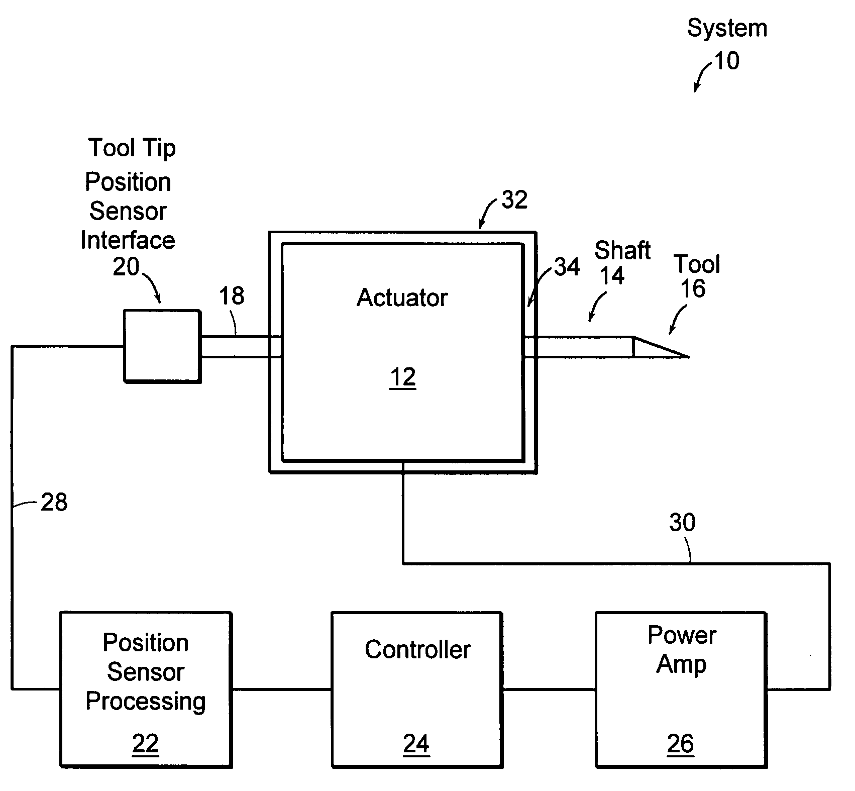
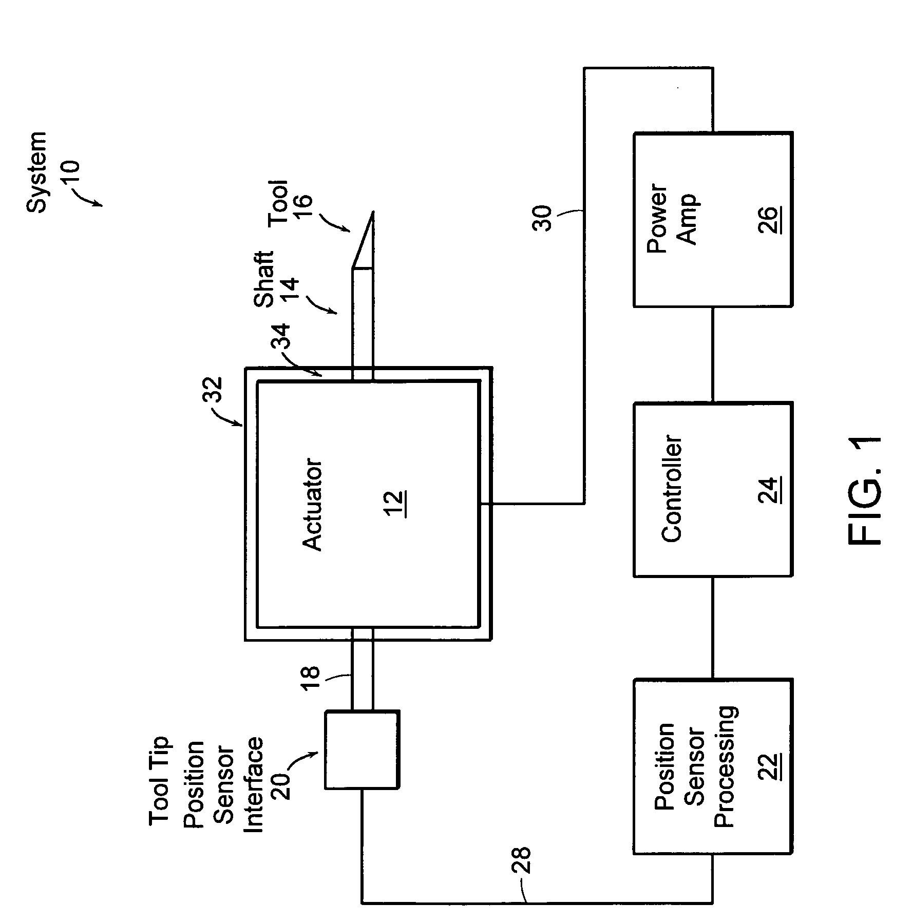
[0045]FIG. 1 illustrates a schematic representation of a system 10 consisting of linear fast tool servo (linear FTS) 12 having a shaft 14 and tool 16, a tool tip position sensor 18 having a position sensor interface 20 and a position sensor control and processing module 22, a controller 24 and a power amplifier 26. FTS 12 is an electromagnetic device that operates at very high speeds while allowing extremely precise control of tool tip 16. In fact, embodiments of FTS can operate at speeds on the order of 20 kHz while providing tool position accuracies on the order of 1 nanometer (nm).

[0046] Position sensor 18 is communicatively coupled to shaft 14 in a manner allowing the position of tool 16 to be monitored with respect to a reference. The reference may be a face 34 of a housing 32 surrounding components making up FTS 12, or the reference may be a gap between magnetic components, a point located external to housing 32, etc. Position sensor 18 may also include an interface 20 and co...


PUM

PropertyMeasurementUnit
frequencyaaaaaaaaaa
diameteraaaaaaaaaa
thicknessaaaaaaaaaa

Abstract

The preferred embodiments of the present invention are directed to high bandwidth positioning systems such as fast tool servos (FTS). The applications of this invention include, for example, diamond turning of mold with structured surface for mass production of films for brightness enhancement and controlled reflectivity, diamond turning of molds for contact lens and micro-optical positioning devices. Preferred embodiments of the fast tool servo can have a closed-loop bandwidth of approximately 20±5 kHz, with acceleration of up to approximately 1000 G or more. The resolution or position error is approximately 1 nm root mean square (RMS). In a preferred embodiment, the full stroke of 50 μm can be achieved up tol kHz operation.

Description

CROSS REFERENCE TO RELATED APPLICATIONS [0001] This patent application claims the benefit of U.S. Provisional Patent Application 60 / 517,216, having a filing date of Oct. 31, 2003 and U.S. Provisional Patent Application 60 / 619,183, having a filing date of Oct. 15, 2004, these applications being incorporated herein by reference in their entirety.BACKGROUND OF THE INVENTION [0002] Fast Tool Servo (FTS) technology can enable precise positioning or manufacturing of complicated sculptured surfaces having nanometer-scale resolution requirements. Such surfaces are used in a wide range of products, including films for brightness enhancement and controlled reflectivity, sine wave ring mirrors used in carbon dioxide (CO2) laser resonators, molds for contact lenses, as well as in micro-optical devices such as Fresnel lenses, multi-focal lenses and microlens arrays. The limits on stroke, bandwidth, acceleration, and position noise of the FTS impose limits on the types, quality, and rate at which...

Claims


Application Information

Patent Timeline
Patent Type & Authority Applications(United States)
IPC IPC(8): B23B1/00B23B3/00B23B5/36H02K33/00H02K33/16
CPCB23B1/00B23B5/36H02K33/16Y10T82/30
Inventor LU, XIAODONGTRUMPER, DAVID L.
Owner MASSACHUSETTS INST OF TECH
Why Eureka
Try Eureka