Measurement of large strains in ropes using plastic optical fibers

a technology of optical fibers and large strains, which is applied in the direction of distance measurement, force/torque/work measurement apparatus, instruments, etc., can solve the problems of reducing the strength of the rope, and causing damage to the rop

Inactive Publication Date: 2005-10-13
WILLIAMS JERRY GENE +2
View PDF4 Cites 74 Cited by
  • Summary
  • Abstract
  • Description
  • Claims
  • Application Information

AI Technical Summary

Benefits of technology

[0053] In accordance with the present invention, there is provided a method for the direct in situ measurement of large strains on the order of 0- to 15-percent or more in ropes using plastic optical fibers and Optical Time-Domain Reflectometer or other light time-of-flight measurement instrumentation such as Optical Frequency Domain Reflectometry. A plastic protective sheath and ingress-egress guides are incorporated to protect the plastic optical fiber in the marine environment and in the transition region of ingress into and egress out of the rope. A small braided rope optics carrier with minimal intrusion in the rope cross-section is one embodiment of the method which allows lateral compressive forces to be applied to the plastic optical fiber and restrain it from slipping and thus experience the same strain as the rope. The braided rope optics carrier can be incorporated in numerous rope configurations including braided, twisted, helical or wire rope constructions. A method is described for etching reflective interfaces at selected locations along the length of the plastic optical fiber. The method allows multiple reflective interfaces within a single fiber and thus provides the capability to measure strain along the entire length of the rope and within discrete length segments along the fiber's length. Multiplexing of the light signal allows monitoring of several plastic optical fibers and multiple segments within a fiber using a single light time-of-flight instrument. Interpretation of the data allows one to calculate the accumulated strain at any point in time and to determine if the rope has experienced local damage. Perfluorocarbon and polymethyl methacrylate are representative plastic optical fibers with the ability to track the cyclical large strains typically experienced by ropes used in the marine industry including mooring ropes used for station keeping on offshore platforms and marine ropes used to dock vessels.

Problems solved by technology

Ropes carry high tension loads and the service environment is often hostile, potentially causing damage to ropes.
The extreme conditions in the marine environment, especially under extreme loading conditions such as hurricanes, and due to possible damage caused by the intrusion of lines and cables from adjacent operations, can reduce the strength of the ropes.
Despite the use of current inspection procedures, however, there have been accidents, damages to property and equipment, injuries and deaths due to unexpected rope failures.
On the other hand, the loss of signal in a plastic fiber is a definite challenge since their attenuation (loss of light energy) is much greater.
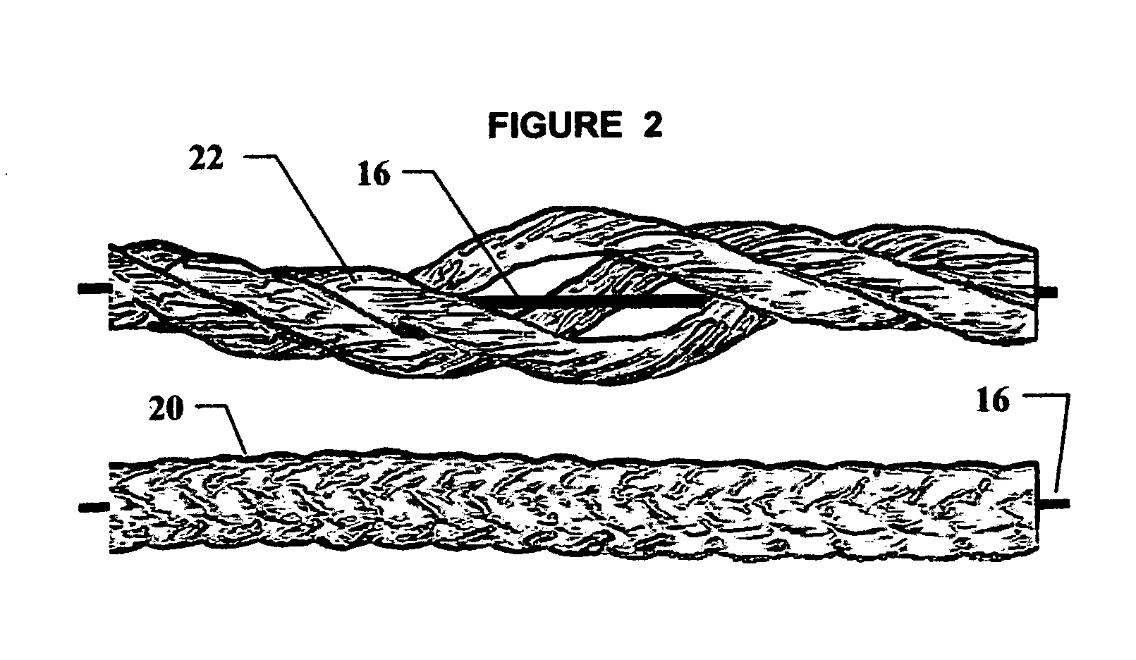
One of the primary challenges is how best to integrate the optical fiber into the assembly to insure that the optical fiber experiences the same strain as the mooring rope and is protected such that it is not damaged during a long service life.
Too much lateral compressive pressure, however, can also create attenuation and change the light transmission characteristics.
Some resolution problems are inherently characteristic of measurements on short length specimens characteristic of these lab tests (2-ft), which will not occur for longer length ropes typically used in marine applications.
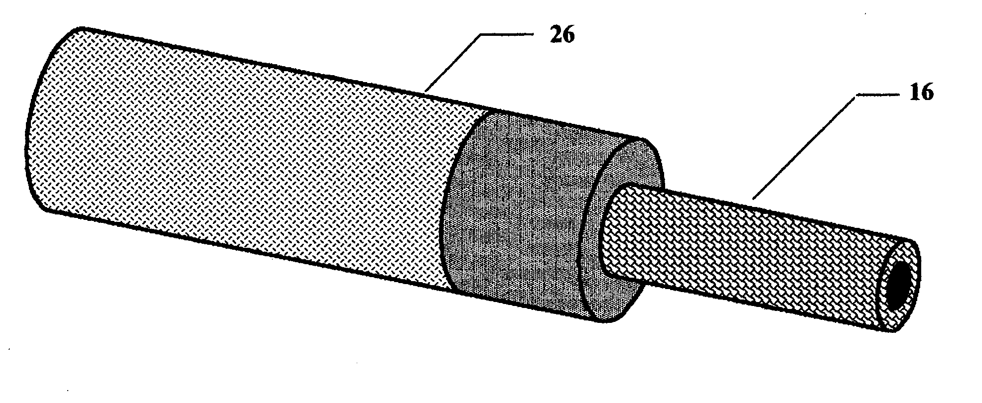
One of the most important discoveries found in these early tests was that a braided jacket with a braid angle of around 45-degrees surrounding the near axial oriented polyester fibers was inadequate to locally restrain the plastic optical fiber.
As discussed above, local bending of the optical fiber can create significant attenuation, which limits the fibers ability to transmit light, and consequently the length of rope that can be strain monitored with a single plastic optical fiber.
It was found at very high strains (around 10 percent) that the braided rope imposed small radius curvature on the optical fiber-plastic cover bundle at the entry point and caused significant loss of light signal to the OTDR.
Synthetic fiber mooring ropes segments are limited by transportation and handling to lengths of around 2500 feet.
The practical problem of how to bring the light signal from remote sections of a long length of rope longer than that permissible by a single plastic optical fiber is still under development.
In time the attenuation characteristics of plastic optical fibers will improve; however, at present, it unlikely that a single plastic optical fiber will have sufficient limited light loss to be able to monitor a length of 10,000 feet or more.
First, glass optical fibers can be used which have lower attenuation, but as noted above, glass optical fibers cannot directly bridge the long length because strains typically imposed exceed the breaking strain of glass fibers.
This is cumbersome requiring power at ocean depths and has practical limitations.
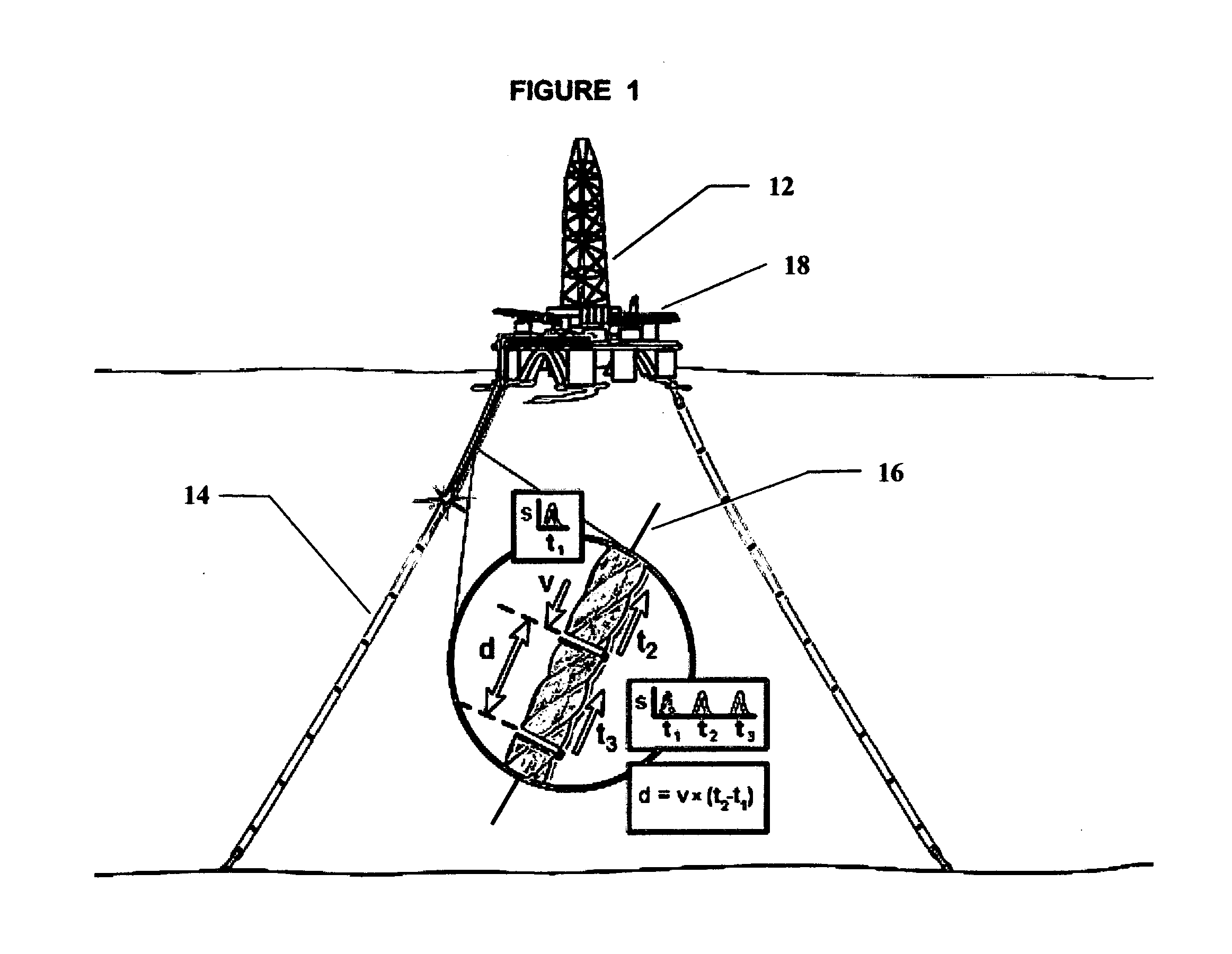
OTDR instrumentation could be located remotely and transmit the data rather than the light signal to the surface, but this would impose severe complications.
This approach is being conducted because no strain measurement or other system is available to provide more definitive in situ inspection.
The method taught in U.S. Pat. No. 5,182,779 is not applicable to the direct measure of large strain in ropes because the small ultimate strain capability of glass optical fibers does not allow it.
Although glass fibers have an ultimate strain capability on the order of 2 percent, practical limitations impose a strain limit of less than 1 percent.
Bridge and elevator cables are typically steel wire rope and as such the design strain is normally limited to less than 0.2 percent (60,000 psi stress) and if constructed of synthetic fiber have practical deformation limitations and associated low strains.
The method is thus limited to measurement in metallic and composite structures experiencing small strains.
The prestressing approach is not practical for mooring ropes used to maintain position in offshore platforms and the inventors do not teach how to use the technique without overstressing the glass optical fiber even for small strains.
Patent 5,182,779 cannot serve the purposes of measuring large strains in ropes such as experienced in service by ropes using in the marine industry including offshore platform mooring ropes.
Measurement of local strains in typical metallic and composite structures using straight glass optical fibers and OTDR instrumentation is not practical because of the extremely low sensitivity of the OTDR method when used for short gage lengths.
In addition, typical strains in a rope are an order of magnitude larger than strains in typical metallic or composite structures making glass optical fibers unacceptable.
The telecommunication industry uses glass optical fiber because the attenuation of plastic fibers over long lengths would be unacceptable.
The patent teaches these uses for glass optical fiber, but does not address the use of plastic optical fiber or measuring strain in ropes.
The deficiency of the visual inspection method is that it reveals nothing about the load-strain history of the rope or the state of internal wear or degradation.
For such large ropes, one cannot visually detect internal wear or damage.
In addition, it is difficult to reliably inspect long length mooring ropes in situ using, for example, ROV technology.
The short rope segment removal and testing method for determining “fitness for service” of mooring ropes used for station keeping of offshore platforms is an expensive operation and the removal activity itself introduces operational hazards.
The short length rope test segments thus can provide a weaker link than the longer length segments which constitute the remainder of the rope, and their introduction can thus reduce the overall strength of the rope in service.
This is a large inclusion which interferes with the architectural design of the rope and whose presence could affect the mechanical properties of the rope.
More importantly, the indirect measurement of strain is much less accurate and conclusive than the direct measurement of strain in the mooring rope permitted by the large strain capability of plastic optical fibers described herein.
Although the developers claim that the technique can detect local damage, the magnitude of the local strain is not measured.

Method used


Image

  • Measurement of large strains in ropes using plastic optical fibers
  • Measurement of large strains in ropes using plastic optical fibers
  • Measurement of large strains in ropes using plastic optical fibers

Examples


Embodiment Construction

[0067] Generally speaking, the invention pertains to a method for making large in situ strain measurements, in particular, strain experienced in service by ropes such as offshore platform mooring ropes or docking ropes using a plastic optical fiber and a time-of-flight of light measurement technique involving instrumentation such as Optical Time Domain Reflectometry or Optical Frequency Domain Reflectometry. The application on an offshore platform mooring line features multiple sets of plastic optical fibers, multiple reflective surface within the plastic optical fiber to allow strain to be measured in discrete lengths of plastic optical fiber and thus the rope, and multiplexing to allow large numbers of measurements to be taken by a single Optical Time Domain Reflectometry or Optical Frequency Domain Reflectometry instrument.

[0068] Now referring to FIG. 1 through 7, which teach the details of a method which can be exercised to achieve accurate reliable data for the measurement of ...


PUM

PropertyMeasurementUnit
radiusaaaaaaaaaa
lengthaaaaaaaaaa
braid angleaaaaaaaaaa

Abstract

A method for the direct measurement of large strains in ropes in situ using a plastic optical fiber, for example, perfluorocarbon or polymethyl methacrylate and Optical Time-Domain Reflectometer or other light time-of-flight measurement instrumentation. Protective sheaths and guides are incorporated to protect the plastic optical fiber. In one embodiment, a small rope is braided around the plastic optical fiber to impose lateral compressive forces to restrain the plastic optical fiber from slipping and thus experience the same strain as the rope. Methods are described for making reflective interfaces along the length of the plastic optical fiber and to provide the capability to measure strain within discrete segments of the rope. Interpretation of the data allows one to calculate the accumulated strain at any point in time and to determine if the rope has experienced local damage.

Description

[0001] This application claims priority from U.S. Provisional Patent Application No. 60 / 377,421, filed May 3, 2002 entitled “Optical Fiber Sensor for Measuring Strain in Synthetic Ropes”, and U.S. Provisional Application No. 60 / 443,311 filed Jan. 29, 2003 entitled “Method and Apparatus for Measuring Large Strains in Synthetic Fiber Ropes”; both herein incorporated by reference in their entirety.FIELD OF THE INVENTION [0002] The present invention relates to use of a plastic optical fiber and optical time-domain reflectometry or other instrumentation for the direct, in situ measurement of large strains imposed on ropes during service and, more particularly, in synthetic fiber ropes. The plastic optical fiber is integrated into the rope in several configurations which allow the plastic optical fiber to experience the same strain as the rope including the capability to monitor strain during cyclical loading. The method provides the capability to make multiple strain measurements in a si...

Claims


Application Information

Patent Timeline
Patent Type & Authority Applications(United States)
IPC IPC(8): G01D5/353G01L5/10G02B6/10
CPCD04C1/02G01L5/105G01D5/35354G01D5/35316D07B1/145D07B2201/2096D07B2301/5577D07B2501/2061
Inventor WILLIAMS, JERRY GENESMITH, DAVID BARTONMUHS, JEFFREY DAVID
Owner WILLIAMS JERRY GENE
Why Eureka
Try Eureka