

Member having photocatalytic function and method for manufacture thereof
- Summary
- Abstract
- Description
- Claims
- Application Information
AI Technical Summary
Benefits of technology
Problems solved by technology
Method used
Image

Examples
Embodiment Construction
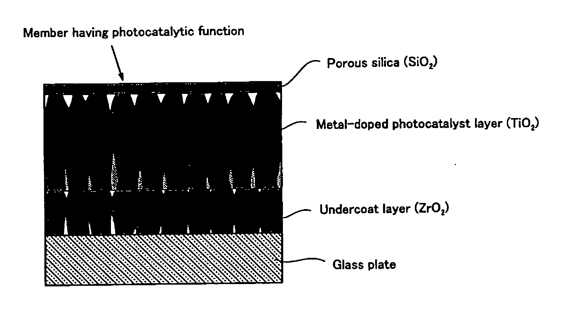
[0054] A detailed description will be made below on embodiments of the present invention referring to the accompanying drawings. FIG. 3 is a schematic cross-sectional view illustrating a member having a photocatalytic function according to the present invention. In this typical example, a layer of crystalline ZrO2 is formed as an undercoat layer in a thickness of 56 nm on the surface of a glass plate as a substrate, a layer of crystalline TiO2 in which metal is doped is formed as a photocatalyst layer in a thickness of 140 nm on the ZrO2 layer, and a porous SiO2 layer is formed in a thickness of 5 nm on the TiO2 layer so as to enhance the hydrophilicity.
[0055] The above-described ZrO2 layer, TiO2 layer and SiO2 layer are formed by a sputtering method. Metal such as tin (Sn), zinc (Zn), molybdenum (Mo) or iron (Fe) is doped at the time of forming the TiO2 layer.
[0056] Table 1 shows the film configuration, the methods for forming the peel preventing layer, the undercoat layer, the p...
PUM
| Property | Measurement | Unit |
|---|---|---|
| Temperature | aaaaa | aaaaa |
| Fraction | aaaaa | aaaaa |
| Percent by mass | aaaaa | aaaaa |
Abstract
Description
Claims
Application Information