
High-performance and low-cost plastic solar cells

Inactive Publication Date: 2005-10-27
YANG YANG +1
View PDF2 Cites 18 Cited by
  • Summary
  • Abstract
  • Description
  • Claims
  • Application Information

AI Technical Summary

Benefits of technology

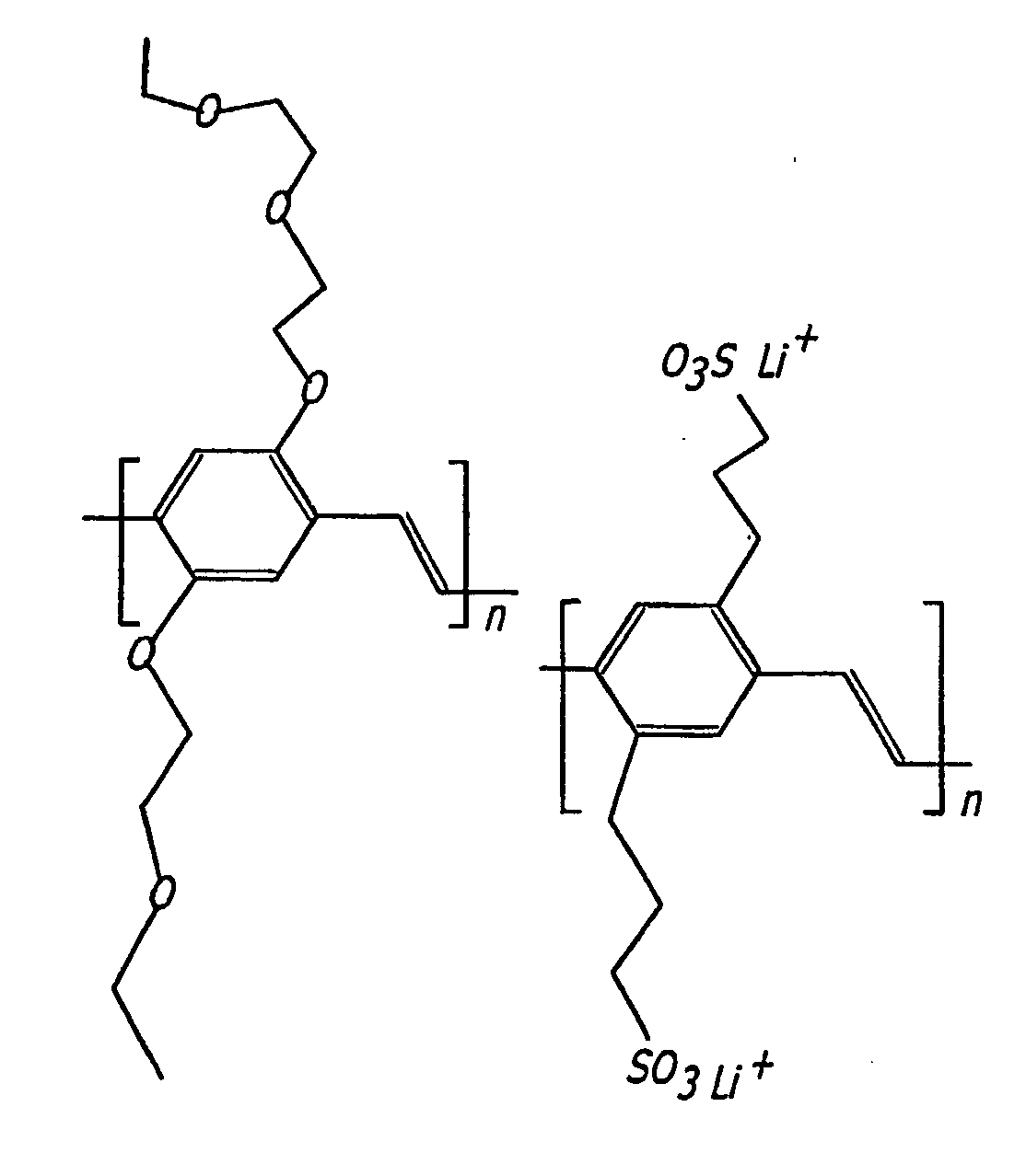
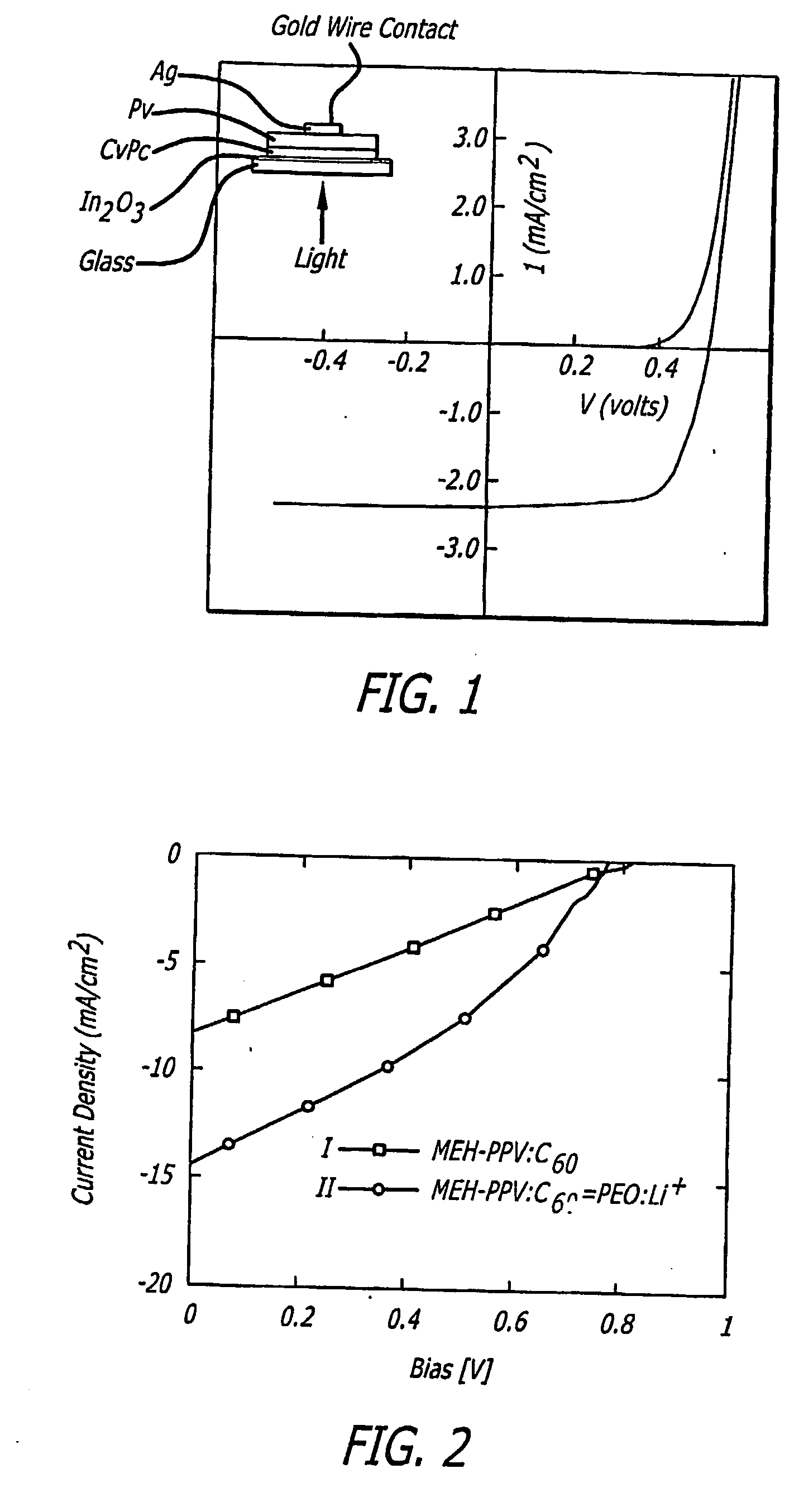
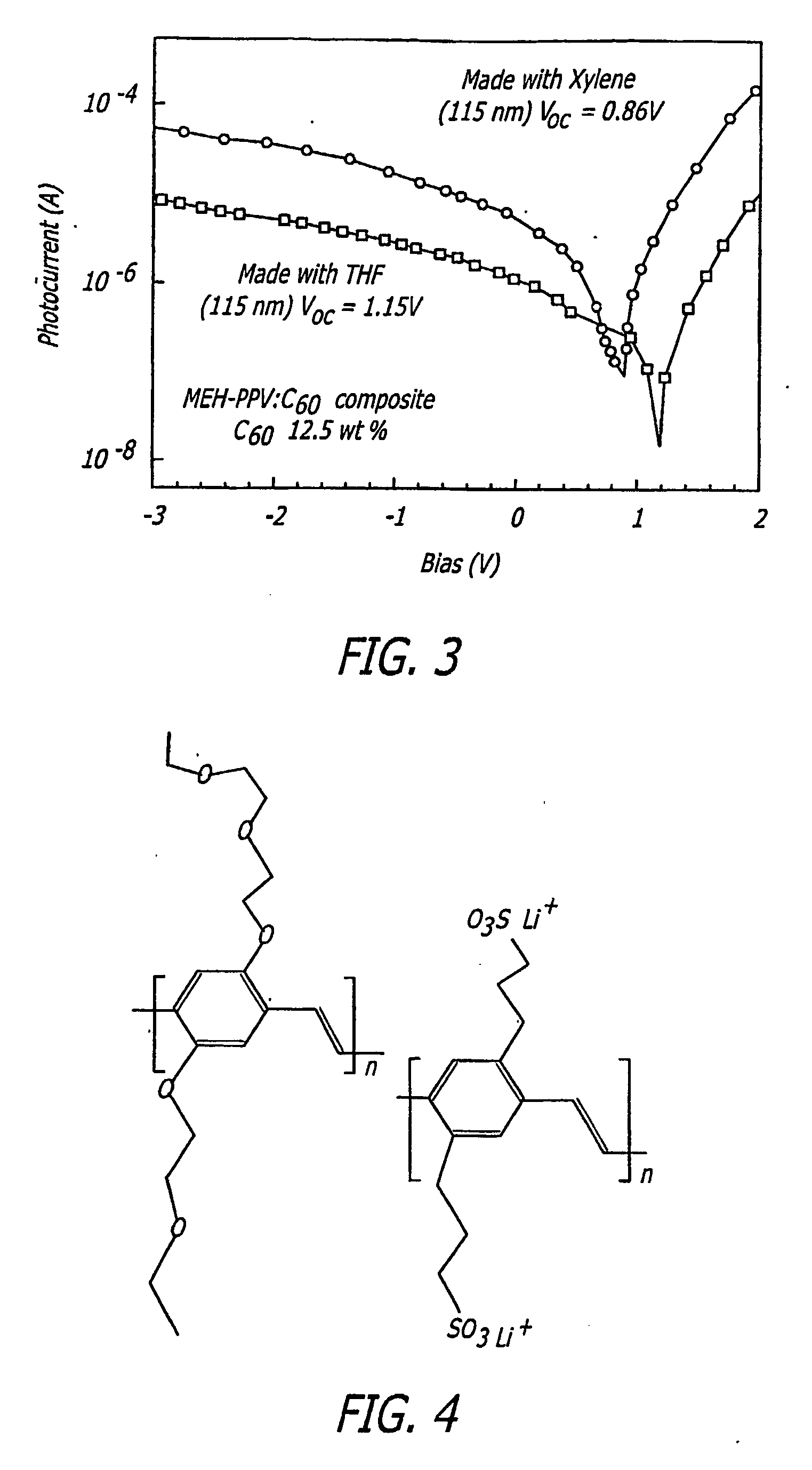
[0010] The present invention enhances the conversion efficiency of plastic (polymer) solar cells by improving the carrier transport of the polymer that is used as the photovoltaic material. In one example of the invention, we have doubled the efficiency of a plastic solar cell by adding a small amount of electrolyte to the polymer. This is mainly attributed to the improvement of carrier transport. However, the reasons for the improvement are not entirely known. In another example, we also found that the carrier transport in a polymer can be dramatically improved by selecting specific polymer morphologies. By combining these two aspects of the present invention, one is able to significantly improve the efficiency of current plastic solar cells. Judging by the current record of 2.5% conversion efficiency (demonstrated by Sariciftci et al.), a 5% efficiency is achievable in accordance with this invention. The present invention provides for the fabricating of efficient and stable plastic solar cells with a low-cost continuous polymer coating process.
[0011] The present invention involves making efficient plastic solar cells by improving their carrier transport capability by the following methods: (a) improving material conductivity by blending a small amount of electrolyte into the polymer films; (b) by fine tuning polymer morphology so that the carrier mobility increases. A 5% power efficiency can be achieved based on our preliminary results. This number (5%) is similar to or better than the efficiency achieved by amorphous silicon solar cells.
[0012] Our invention significantly enhances the Jsc of plastic solar cells. By adding a very small amount of ionic electrolyte into the plastic solar cells (0.01 to 5 percent by weight), it was discovered that the Jsc was doubled. Our invention is used with device structures that are typical polymer solar cells, consisting of a layer of polymer thin film sandwiched between a transparent anode (indium tin-oxide, ITO) and a cathode.

Problems solved by technology

However, the reasons for the improvement are not entirely known.

Method used


Image

  • High-performance and low-cost plastic solar cells
  • High-performance and low-cost plastic solar cells
  • High-performance and low-cost plastic solar cells

Examples


Embodiment Construction

[0021] An exemplary solar cell in accordance with the present invention is shown generally at 10 in FIG. 7. The solar cell 10 includes an active material in the form of a photovoltaic film 12. The photovoltaic film 12 has a first side 20 and a second side 18. The photovoltaic film 12 is sandwiched between a transparent anode 16 and a cathode 14. Sunlight or light from another source passes through the transparent anode 16 as represented by arrow 22. The structure and use of the solar cell 10 is basically the same as existing solar cells that use organic materials as the photovoltaic film. The principal difference is that the active material provided in accordance with the present invention has a conversion efficiency that is much higher than was previously possible using organic materials. The active material in accordance with the present invention is a mixture of a semi-conducting polymer and an ionic electrolyte. The ionic electrolyte is present in the mixture in an amount rangin...


PUM

PropertyMeasurementUnit
Percent by massaaaaaaaaaa

Abstract

A solar cell that includes a high efficiency thin film plastic (polymer) as the active material. The active material includes a mixture of a semi-conducting polymer and an ionic electrolyte. The semi-conducting polymer is made up of a ptype polymer and an n-type electron acceptor. The ionic electrolyte is present in said mixture in an amount ranging from 0.01 to 5 weight percent.

Description

BACKGROUND OF THE INVENTION [0001] 1. Field of the Invention [0002] The present invention relates generally to the conversion of light into electrical energy using solar (photovoltaic) cells that utilize a polymer-based material in place of silicon. More particularly, the present invention involves improving the conversion efficiency of plastic photovoltaic materials in order to provide a low cost and efficient plastic solar cell. [0003] 2. Description of Related Art [0004] The publications and other reference materials referred to herein to describe the background of the invention and to provide additional detail regarding its practice are hereby incorporated by reference. For convenience, the reference materials are identified by author and grouped in the appended bibliography. [0005] It is generally agreed that fossil fuels cannot last forever. The use of fossil fuels also causes serious environmental problems, such as the greenhouse effect, air pollution and acid rain, etc. Thus...

Claims


Application Information

Patent Timeline
IPC IPC(8): H01L31/04H01G9/20H01L31/00H01L31/0256H01L31/18H01L51/00H01L51/30H01M14/00
CPCB82Y10/00H01G9/2059H01L51/0036H01L51/0037H01L51/0038Y02E10/549H01L51/0043H01L51/0046H01L51/0048H01L51/4253Y02E10/542H01L51/0039Y02P70/50H10K85/114H10K85/115H10K85/211H10K85/1135H10K85/221H10K85/151H10K85/113H10K30/30H10K30/50
Inventor YANG, YANGCHEN, FANG-CHUNG
Owner YANG YANG
Learn More