Luminescent semi-conductive polymer material, method of preparing the same and organic light emitting element having the same

a semi-conductive polymer and polymer material technology, applied in the field of light emitting materials, can solve the problems of low emission intensity, undesirable bands, lack of mechanical strength,

Active Publication Date: 2005-10-27
N S ENIKOLOPOV INST OF SYNTHETIC POLYMER MATERIALS OF RUSN ACAD OF SCI +1
View PDF4 Cites 6 Cited by
  • Summary
  • Abstract
  • Description
  • Claims
  • Application Information

AI Technical Summary

Benefits of technology

[0016] The polymermaterial of the present invention is capable of luminescence because polymerization by glow discharge occurs at low discharge power values which do

Problems solved by technology

There are several disadvantages associated with these materials, such as a lack of mechanical strength.
The disadvantages of these materials include that the main emission bands are caused by the luminophore and there are undesirable bands caused by the semi-conductive component in the luminescence spectra.
The complex multi-step production method of the starting monomer and the polymer as well as low emission intensity are major disadvantages of these polymer materials.
The disadvantages associated with these materials are that the starting compounds are not easily available and additional steps are required to remove traces of solvent and catalyst.
A disadvantage of these luminescent materials is that the diketopyrrolo-(3,4-c)-pyrrole derivatives are not easily available.
Additionally, due to low molecular weight, the organic material does not provide good mechanical strength in the form of a luminescent layer.
The power used during sputtering of the dye is not less than about 10 W to about 30 W. The use of such large power, however, causes partial destruction of 3-hydroxyflavone as can be seen from the gas phase mass-spectrums.
The disadvantages of this method are that the resultant luminescent material is unstable during storage and a deterioration of the emission characteristics occurs after maintaining the material in air for several hours.
Also, further disadvantages include a large energy consumption and high working frequency (about 13.56 MHz) which, when used in a commercial scale equipment, requires the use of special safety means for protection of the personnel.
The other drawback is that the method requires the use of a special gas-carrier (argon).

Method used


Image

  • Luminescent semi-conductive polymer material, method of preparing the same and organic light emitting element having the same
  • Luminescent semi-conductive polymer material, method of preparing the same and organic light emitting element having the same
  • Luminescent semi-conductive polymer material, method of preparing the same and organic light emitting element having the same

Examples


specific example 1

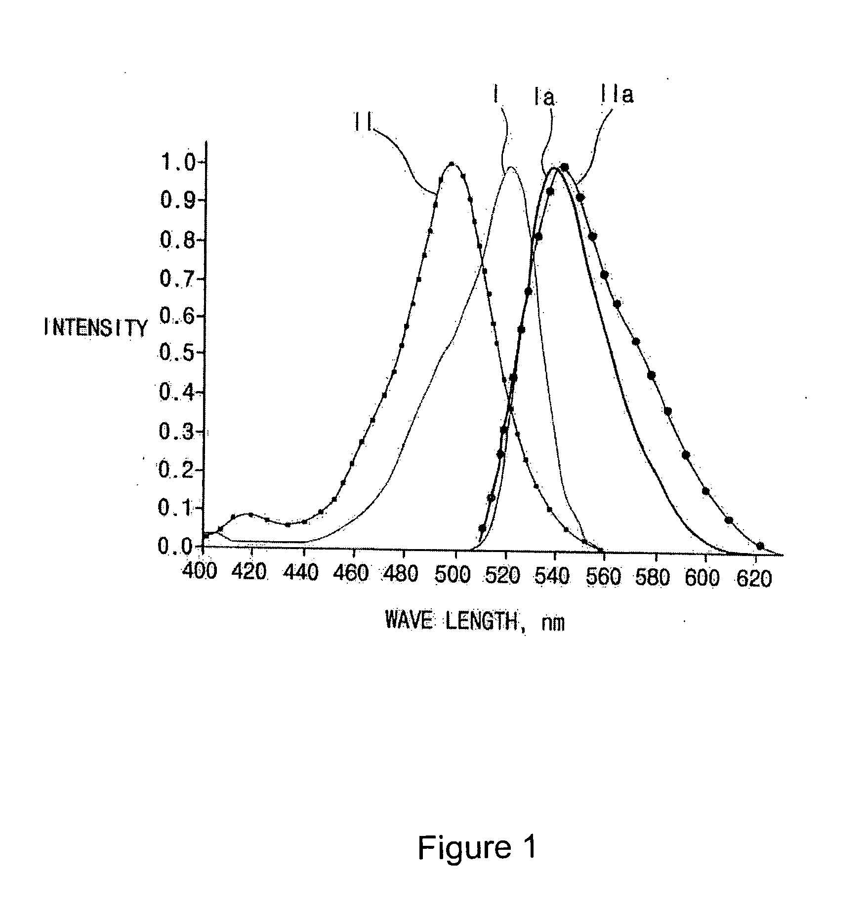
[0023] The polymerization of 1,3,5,7,8-pentamethyl-2,6-diethylpyrromethene difluoroborate complex (pyrromethene 567) was carried out by glow discharge at a temperature of about 250° C., at the discharge power of 0.5 W and a residual pressure of about 10−2 Pa for about 2 minutes. A polymer layer was deposited onto a substrate made of quartz glass having a conductive coating and then deposited onto one of the electrodes. The resultant layer had a thickness of about 0.01 μm, an electrical conductivity of about 1×10⁻¹⁰ S / cm, a luminescence maximum in a spectrum region in the range of about 540 nm to about 544 m with a half-width of the luminescence band in the range of about 55 nm to about 60 nm, and a quantum yield of photoluminescence of about 0.8.

specific example 2

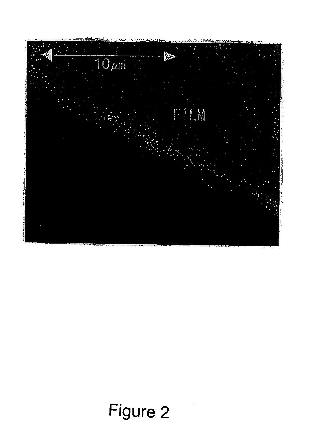
[0024] A luminescent polymer material layer was prepared similar to Example 1, but using the following conditions. The polymerization was conducted at the temperature of about 350° C., the discharge power was about 3 W, the residual pressure was about 10−10 Pa and the duration time was about 120 minutes. The resultant layer was deposited on a silicon substrate placed on one of the electrodes and had a thickness of about 10 μm, an electric conductivity of about 5×10⁻¹⁰ S / cm, a luminescence maximum in a spectrum region in the range of about 575 nm to about 585 nm with a half-width of the luminescence band in the range of about 65 nm to about 75 nm, and quantum yield of photoluminescence of about 0.6.

specific example 3

[0025] A luminescent polymer material layer was prepared as in Example 1, but using the following conditions. The polymerization was carried out at a temperature of about 300° C., at a discharge power of about 1.5 W, at a residual pressure of about 5×10⁻² Pa and with a duration time of polymerization of about 60 minutes. The resultant layer was deposited on metal substrate placed between the electrodes and had a thickness of about 5 μm, an electric conductivity of about 2×10⁻¹⁰ S / cm, a luminescence maximum in a spectrum region in the range of about 560 nm to about 570 nm with a half-width of the luminescence band in the range of about 60 nm to about 65 nm, and a quantum yield of photo-luminescence of about 0.68.

Organic Light Emitting Display (OLED) Apparatus

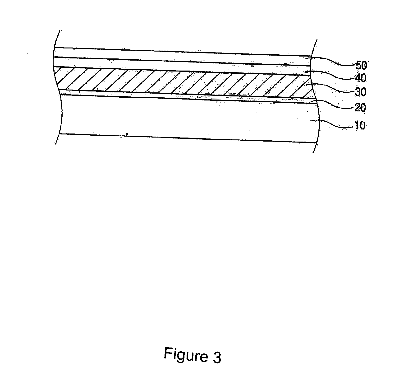
[0026] Referring to FIG. 3, which illustrates an embodiment of the present invention, the OLED apparatus comprises a glass substrate 10, an anode 20, a light emitting layer 30, a cathode 40 and a protecting layer 50. The anode...


PUM

PropertyMeasurementUnit
Temperatureaaaaaaaaaa

Abstract

The present invention is related to a luminescent material generated by polymerization of a pyrromethene complex by glow discharge. The polymer material of the present invention exhibits semi-conductive properties and has a luminescence maximum in a spectrum region in the range of about 540 nm to about 585 nm with a half-width of the luminescence band in the range of about 55 nm to about 75 nm, a quantum yield of photoluminescence in the range of about 0.6 to about 0.8, and an electric conductivity at a temperature of about 20° C. in the range of about 1×10⁻¹⁰ S / cm to about 5×10⁻¹⁰ S / cm. The resultant polymer layer has a thickness in the range of about 0.01 μm to about 10 μm on a substrate placed between or on any of the electrodes. The starting pyrromethene complex may be a 1,3,5,7,8-pentamethyl-2,6-diethylpyrromethene difluoroborate complex (pyrromethene 567). Additionally, the luminescent polymer material may be formed as a layer on a substrate having conductive coating, such as a metal, a dielectric material or semi-conductive material, for example.

Description

CROSS-REFERENCE TO RELATED APPLICATIONS [0001] The present application claims priority to Russian Patent Application No. 2004107865, filed on Mar. 17, 2004, the disclosure of which is hereby incorporated herein by reference in its entirety. FIELD OF THE INVENTION [0002] The present invention is related to light emitting materials that may be used to manufacture light emitting instruments and devices capable of emitting light through photo or electric excitation. In particular, the invention is related to a luminescent semi-conductive material based on a pyrromethene complex. Specifically, the luminescent semi-conductive material of the present invention is obtained by glow discharge polymerization. Additionally, the present invention is related to a method of preparing the luminescent semi-conductive material based on a pyrromethane complex and to an organic light emitting display (OLED) apparatus using the same. BACKGROUND [0003] Electroluminescent materials based on bis-(2-oxybenz...

Claims


Application Information

Patent Timeline
IPC IPC(8): C09K11/06C08G61/12H01B1/00H01L51/00H01L51/50H05B33/14
CPCC08G61/124C09K11/06C09K2211/14H05B33/14H01L51/008H01L51/5012H01L51/0034Y10S428/917H10K85/10H10K85/322H10K50/11
Inventor DRACHEV, ALEXANDR IVANOVICHGHILMAN, ALLA BORISOVNAKUZNETSOV, ALEXANDR ALEXEEVICHSURIN, NIKOLAY MIKHAYLOVICH
Owner N S ENIKOLOPOV INST OF SYNTHETIC POLYMER MATERIALS OF RUSN ACAD OF SCI
Why Eureka
Try Eureka