Electrochromic mirror

a technology of mirrors and electrochromes, applied in the field of interior or exterior rear mirrors, can solve the problems of difficult manufacturing and high manufacturing cost, and achieve the effect of preventing the corrosion of the light-reflecting film

Inactive Publication Date: 2005-10-27
KK TOKAI RIKA DENKI SEISAKUSHO
View PDF4 Cites 9 Cited by
  • Summary
  • Abstract
  • Description
  • Claims
  • Application Information

AI Technical Summary

Benefits of technology

[0014] In consideration of the circumstances above, the present invention provides an electrochromic mirror allowing prevention of the corrosion of the light-reflecting film by the electrolyte solution.

Problems solved by technology

Such electrochromic mirrors have the disadvantage that it is difficult and costly to manufacture them so that they do not cause the above-described phenomenon, in particular when the electrochromic mirrors are used for automobiles, which generally employ curved mirrors.

Method used


Image

  • Electrochromic mirror
  • Electrochromic mirror
  • Electrochromic mirror

Examples


example 1

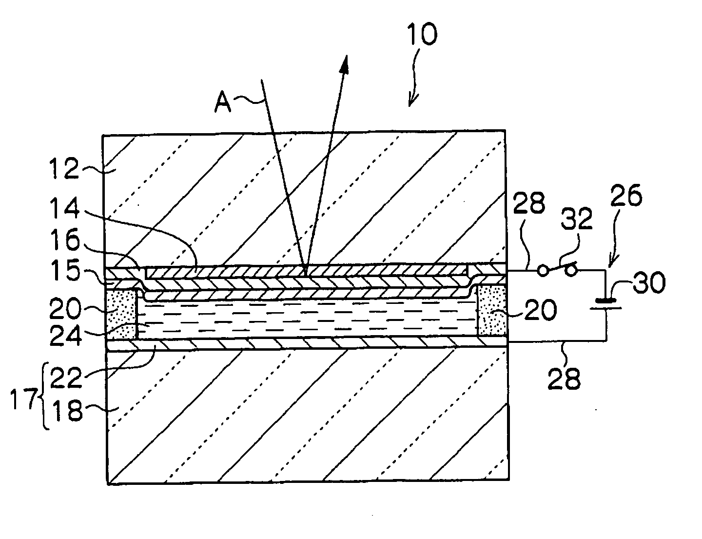
[0058]FIG. 1 is a cross-sectional view illustrating the configuration of an electrochromic mirror 10 according to the first embodiment of the invention.

[0059] The electrochromic mirror 10 has a glass substrate 12 as its transparent substrate. The glass substrate 12 has an electrochromic film 14 that develops color reductively formed on the rear face (bottom surface in FIG. 1) by, for example, means of vacuum deposition in the form of a thin film. The material used for the electrochromic film 14 in the first embodiment is tungsten trioxide (WO3).

[0060] On the side of electrochromic film 14 opposite to the glass substrate 12, a conductive light-reflecting film 16 allowing transmission of hydrogen atoms and having electrical conductivity is formed as a thin film, for example, by means of vacuum deposition. Use of a noble metal in the platinum family such as platinum, rhodium, or palladium, alloys containing the same (e.g., an alloy of silver and an element in platinum family), or the...

example 2

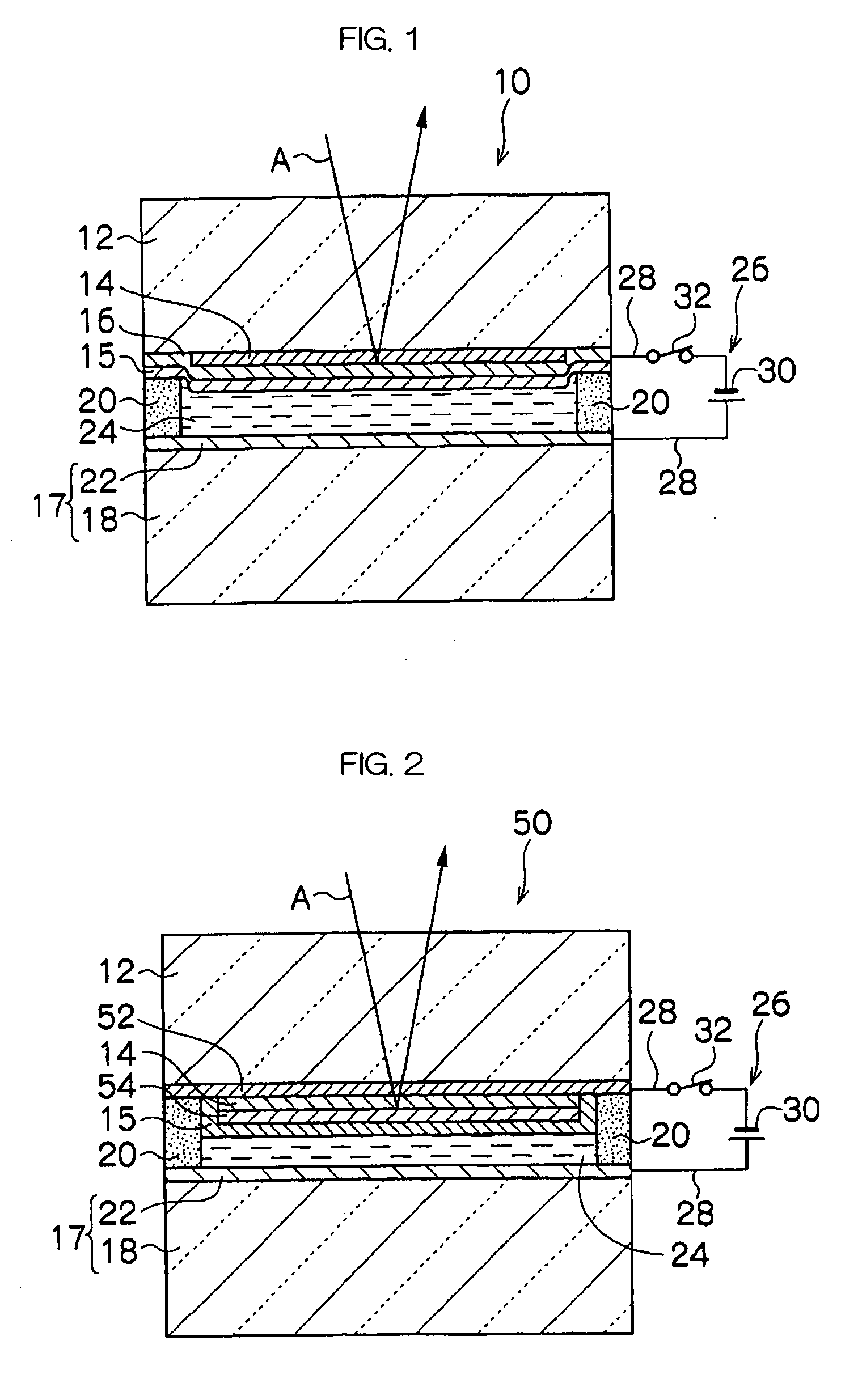
[0075]FIG. 2 is a cross-sectional view illustrating the configuration of an electrochromic mirror 50 according to the second embodiment.

[0076] As shown in FIG. 2, the electrochromic mirror 50 according to the second embodiment has a configuration fundamentally the same as that of the electrochromic mirror 10 according to the first embodiment, but is different in the following features.

[0077] The electrochromic mirror 50 has a glass substrate 12 having a transparent electrode film 52 with electrical conductivity formed as a thin film on the rear face of the glass substrate (bottom surface in FIG. 2) by, for example, means of vacuum deposition. Examples of the material used for the transparent electrode film 52 include tin-doped indium oxide (ITO), fluorine-doped tin oxide (SnO2:F), antimony-doped tin oxide (SnO2:Sb), and the like.

[0078] An electrochromic film 14 similar to the electrochromic film 14 according to the first embodiment is formed as a thin film on the face of transpar...

example 3

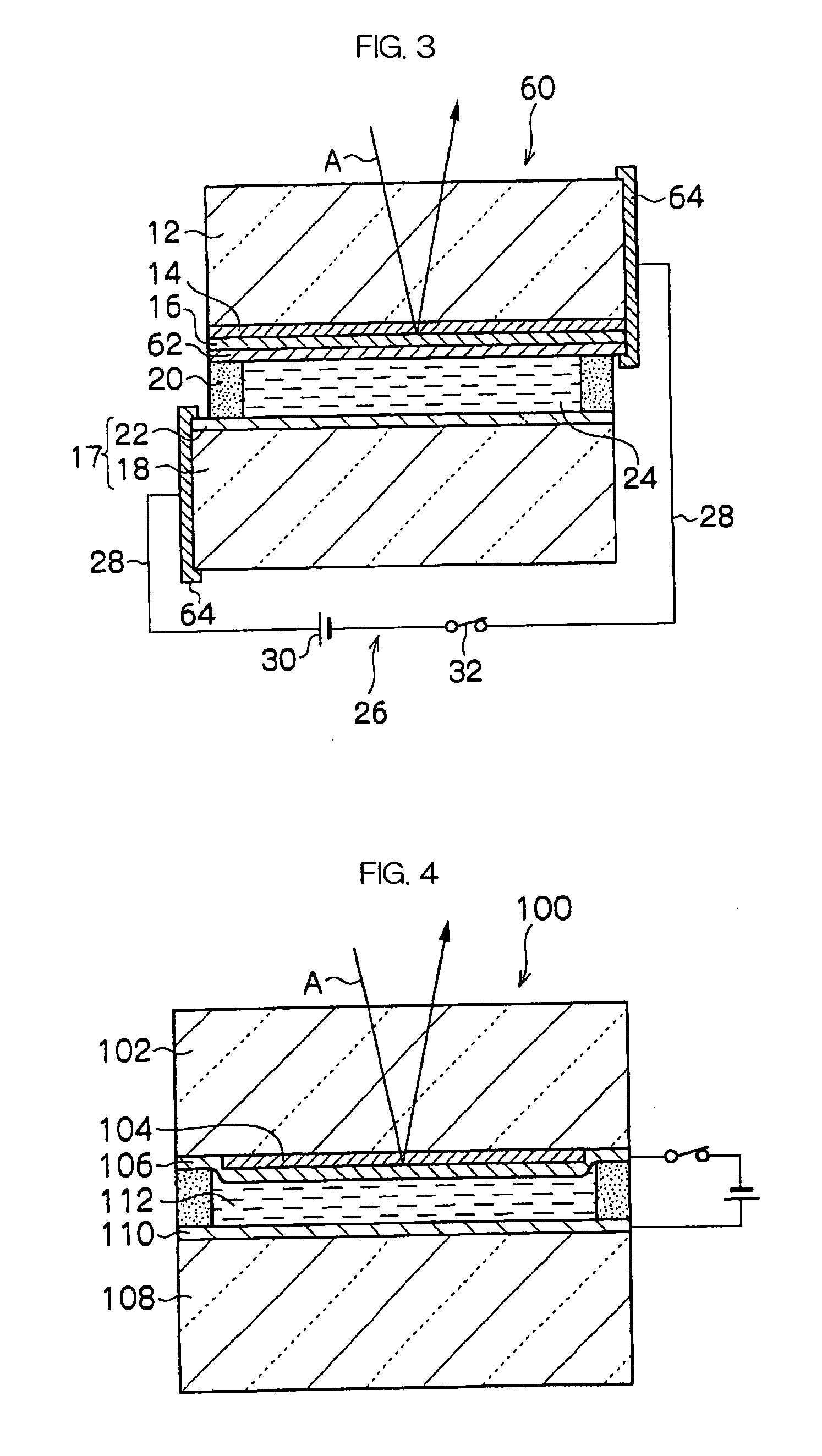
[0091]FIG. 3 is a cross-sectional view illustrating the configuration of an electrochromic mirror 60 according to the third embodiment.

[0092] As shown in FIG. 3, the electrochromic mirror 60 according to the third embodiment has a configuration fundamentally the same as that of the electrochromic mirror 10, but is different therefrom in the following features.

[0093] In the electrochromic mirror 60, a dielectric film 62 having electrical conductivity and hydrogen ion conductivity is formed as a film on the side of conductive light-reflecting film 16 opposite to the electrochromic film 14, for example, by means of vacuum deposition. Favorable examples of the materials used for the dielectric film 62 include tin oxide (SnO2), fluorine-doped tin oxide (SnO2:F), antimony-doped tin oxide (SnO2:Sb), tin-doped indium oxide (ITO), zinc oxide (ZnO), aluminum-doped zinc oxide (ZnO:Al), titanium oxide (TiO2), titanium nitride (TiN), and the like.

[0094] In the electrochromic mirror 60, the gl...


PUM

PropertyMeasurementUnit
electrochromicaaaaaaaaaa
transparentaaaaaaaaaa
electrically conductiveaaaaaaaaaa

Abstract

The present invention provides an electrochromic mirror, comprising a transparent substrate; an electrochromic film that develops color reductively having the transparent substrate on or above the surface thereof; a light-reflecting film allowing transmission of hydrogen or lithium atoms formed on the side of the electrochromic film opposite to the transparent substrate; a substrate having an electrically conductive area at least on one surface facing the light-reflecting film; and an electrolyte solution at least containing a hydrogen ion and an oxidizable material containing neutral molecules or negative ions and that is sealed between the light-reflecting film and the conductive area of the substrate; wherein (i) the light-reflecting film has electrical conductivity, or (ii) a transparent electrode film having electrical conductivity is formed between the transparent substrate and the electrochromic film, further comprising a dielectric film having a hydrogen or lithium ion conductivity formed between the light-reflecting film and the electrolyte solution.

Description

CROSS-REFERENCE TO RELATED APPLICATION [0001] This application claims priority under 35 USC 119 from Japanese Patent Application No, 2004-129666, the disclosure of which is incorporated by reference herein. BACKGROUND OF THE INVENTION [0002] 1. Field of Invention [0003] The present invention relates to an interior or exterior rear mirror applicable for use in vehicles such as automobiles and particularly an electrochromic mirror that changes its reflectance with an applied voltage. [0004] 2. Description of the Related Art [0005] Electrochromic mirrors that change their colors in a coloring reaction of a so-called “electrochromic solution”, a solution that changes its color electrically, are conventionally known (e.g., Japanese Patent No. 2672083). [0006] Japanese Patent No. 2672083 teaches an electrochromic mirror which disposes two glass substrates in parallel with each other at a certain distance. Two transparent electrode films are respectively formed on internal surfaces of thes...

Claims


Application Information

Patent Timeline
Patent Type & Authority Applications(United States)
IPC IPC(8): B60R1/08G02F1/15G02F1/153G02F1/155G02F1/157
CPCG02F2001/1552G02F2201/50G02F2001/1536G02F1/1525B60R1/088
Inventor NAKAHO, JUNICHI
Owner KK TOKAI RIKA DENKI SEISAKUSHO
Why Eureka
Try Eureka