

Hydrogen sensing apparatus and method
a technology of sensing apparatus and water, applied in the direction of liquid/fluent solid measurement, instruments, electrochemical variables of materials, etc., can solve the problems of unable to achieve a breakthrough in this technology, the use of reference gas is awkward, and the chemical stability of the electrolyte/reference interface is not guaranteed.
- Summary
- Abstract
- Description
- Claims
- Application Information
AI Technical Summary
Benefits of technology
Problems solved by technology
Method used
Image

Examples
example 1
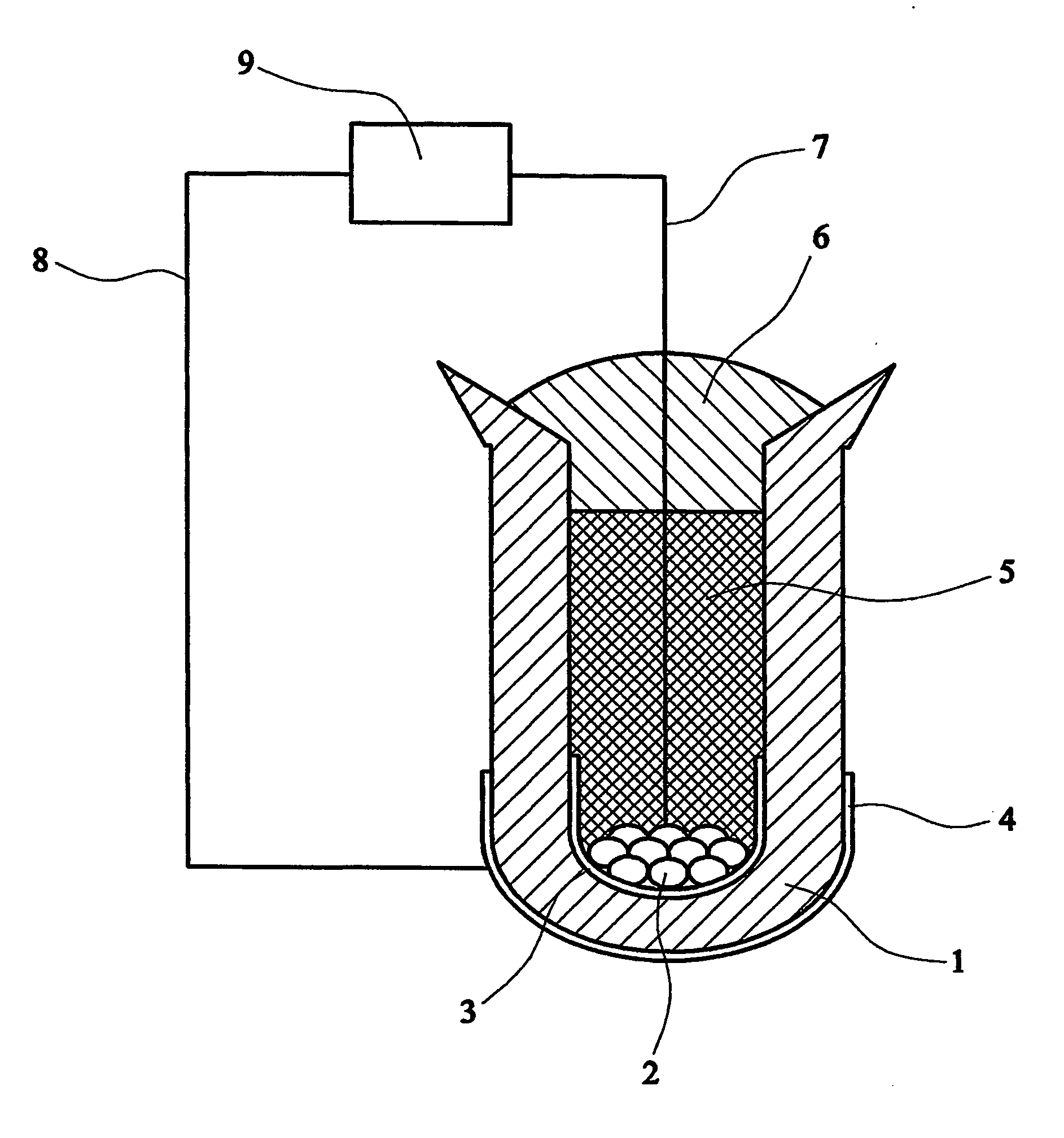
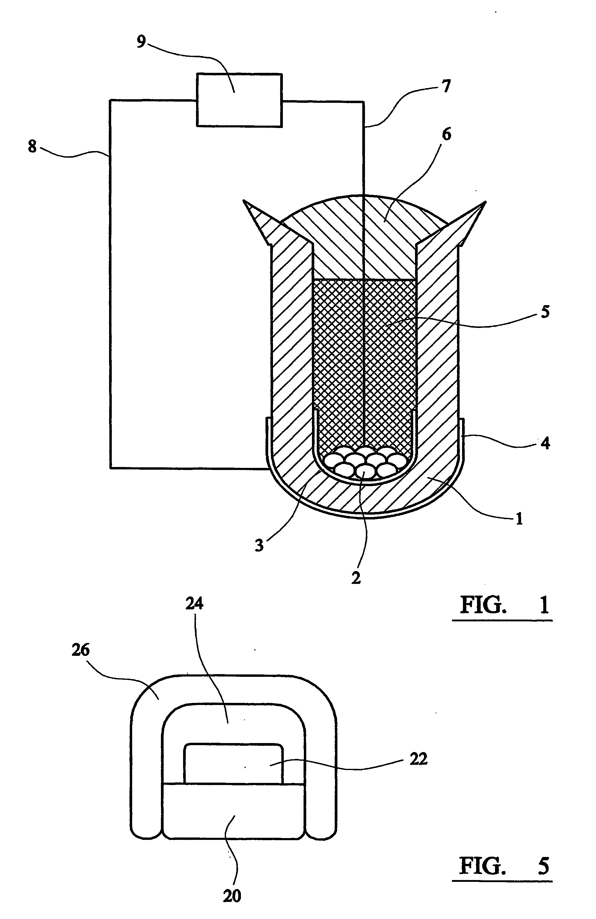
[0034] 40 mg of titanium metal pieces, cut from a grit-blasted sheet of commercial grade 4 titanium metal with a known bulk oxygen content of 3600 ppm by mass, were placed inside a ceramic calcium zirconate thimble. (Grit-blasting was carried out to clean the surfaces of the as-received titanium metal specimen.) The interior of the thimble was then filled with undoped calcium zirconate powder which is inert and acts as a packing material. This was covered with a layer of a laboratory-made, silicon-free, sealing glass powder, which has a melting point of approximately 930° C. To melt the glass and form the seal, the arrangement was heated to around 940° C. in an alumina tube under pure hydrogen. Prior to application, the hydrogen was passed through calcium sulphate to remove traces of moisture and through a suitable metal scrubber to ensure low residual oxygen content. The unit was then exposed to a 1% by volume hydrogen in argon gas mixture at 700° C. and coulometric titration was p...
example 2
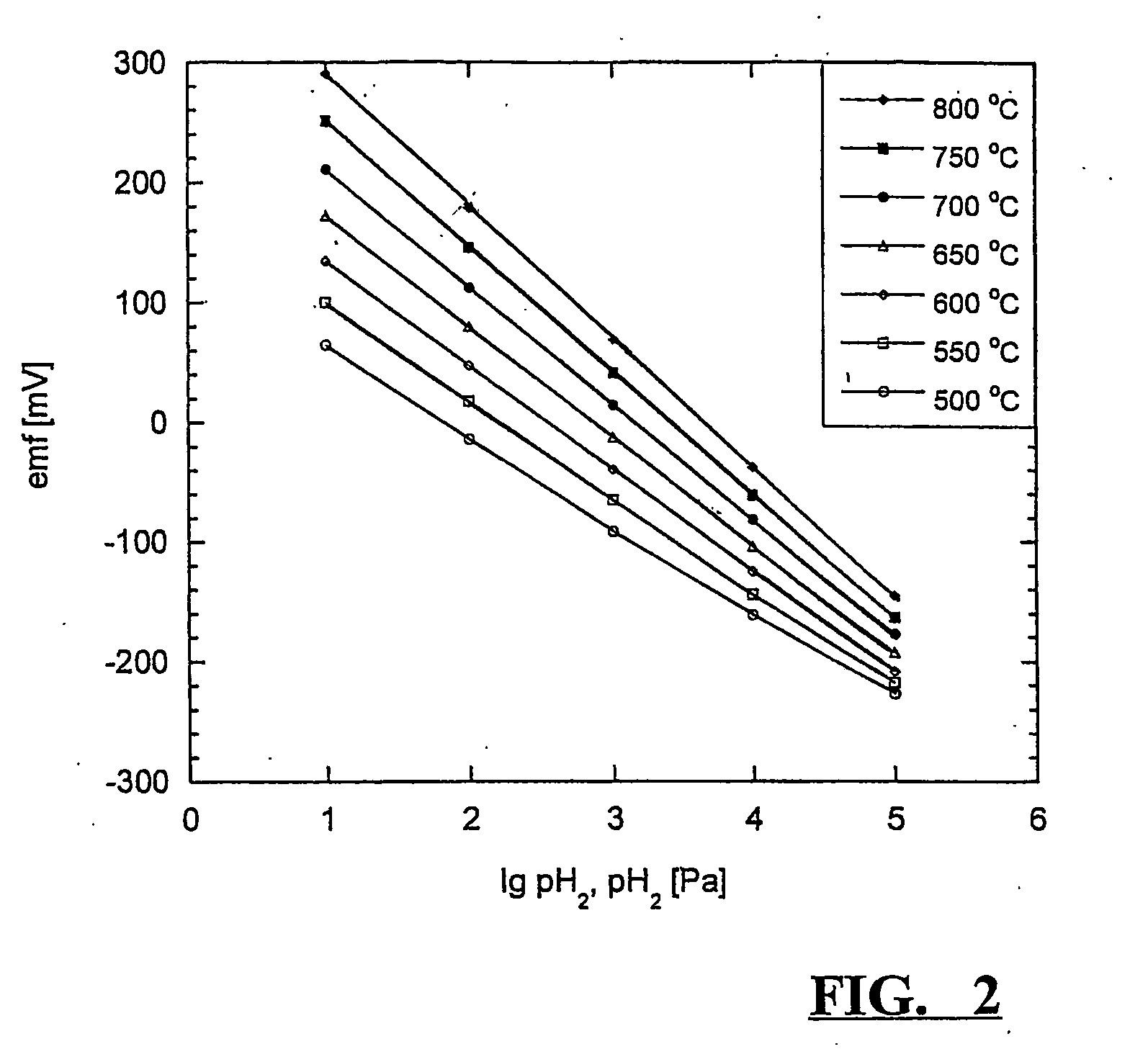
[0037] About 100 mg of zirconium metal were cut from a commercial zirconium wire with a known bulk oxygen content of 1500 ppm by mass and placed inside a ceramic calcium zirconate thimble. The interior of the thimble was filled with yttrium oxide powder, which acts as an inert packing material, and this was covered with a layer of silicon-free sealing glass powder as described in example 1. To melt the glass and form the seal, the arrangement was heated to around 940° C. in an alumina tube under pure hydrogen. By way of this procedure, a zirconium to hydrogen ratio inside the β-zirconium / δ-zirconium two-phase area was established directly. Preconditioning of the sensor was carried out as described in example 1. Sensor measurements were performed between 500° C. and 800° C. in hydrogen / argon mixtures with hydrogen contents of 1, 10 and 100% by volume. Measured emfs are shown in FIG. 3. Agreement with thermodynamic expectations, signal stability and comparability between individual se...
example 3
[0039] About 200 mg of hafnium metal were cut from a commercial hafnium wire with a known oxygen content of 230 ppm by mass and placed inside a ceramic calcium zirconate thimble. 1.0 mg of titanium dioxide was added. The interior of the thimble was filled with yttrium oxide powder, which acts as an inert packing material, and this was covered with a layer of a laboratory-made silicon-free sealing glass powder, which has a melting point of approximately 970° C. To melt the glass and form the seal, the arrangement was heated to around 980° C. in an alumina tube under pure hydrogen. By way of this procedure, a hafnium to hydrogen ratio inside the α-hafnium / δ-hafnium two-phase area was established directly. Preconditioning of the sensor was carried out as described in example 1. Sensor measurements were performed between 600 and 800° C. in hydrogen / argon mixtures with hydrogen contents of 1, 10 and 100% by volume. Measured emfs are shown in FIG. 4. Sensor performance was again found to ...
PUM
| Property | Measurement | Unit |
|---|---|---|
| melting temperature | aaaaa | aaaaa |
| temperatures | aaaaa | aaaaa |
| diameter | aaaaa | aaaaa |
Abstract
Description
Claims
Application Information