
Line-replaceable transmit/receive unit for multi-band active arrays

a phased array and transmit/receive unit technology, applied in the field of array antenna systems, can solve the problems of reducing the power of the beam at the upper frequency extreme, and reducing the efficiency of the beam at the lower operating frequency. , to achieve the effect of facilitating system growth, facilitating system growth, and facilitating system growth

Inactive Publication Date: 2005-11-17
SAAB INC
View PDF3 Cites 24 Cited by
  • Summary
  • Abstract
  • Description
  • Claims
  • Application Information

AI Technical Summary

Benefits of technology

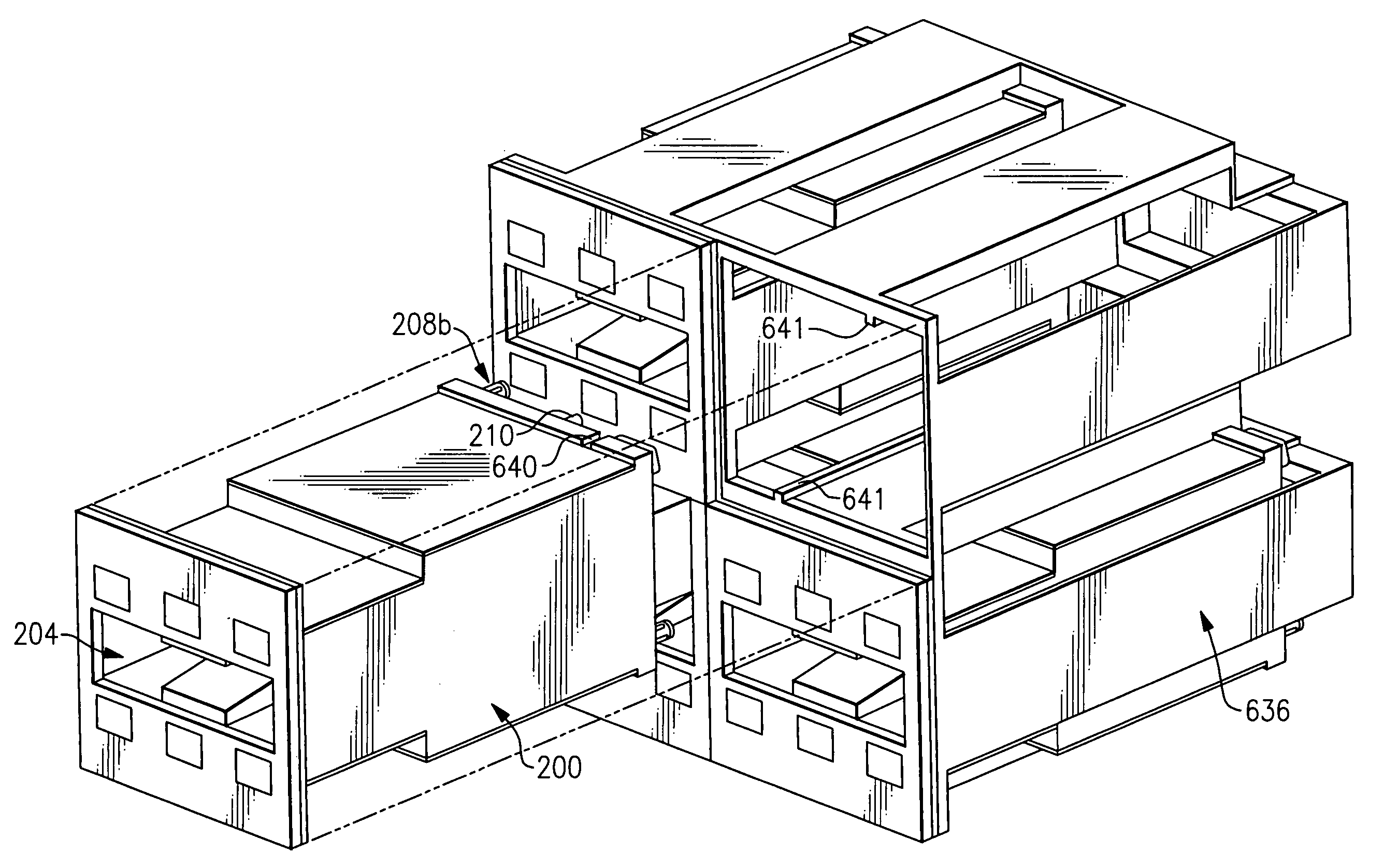
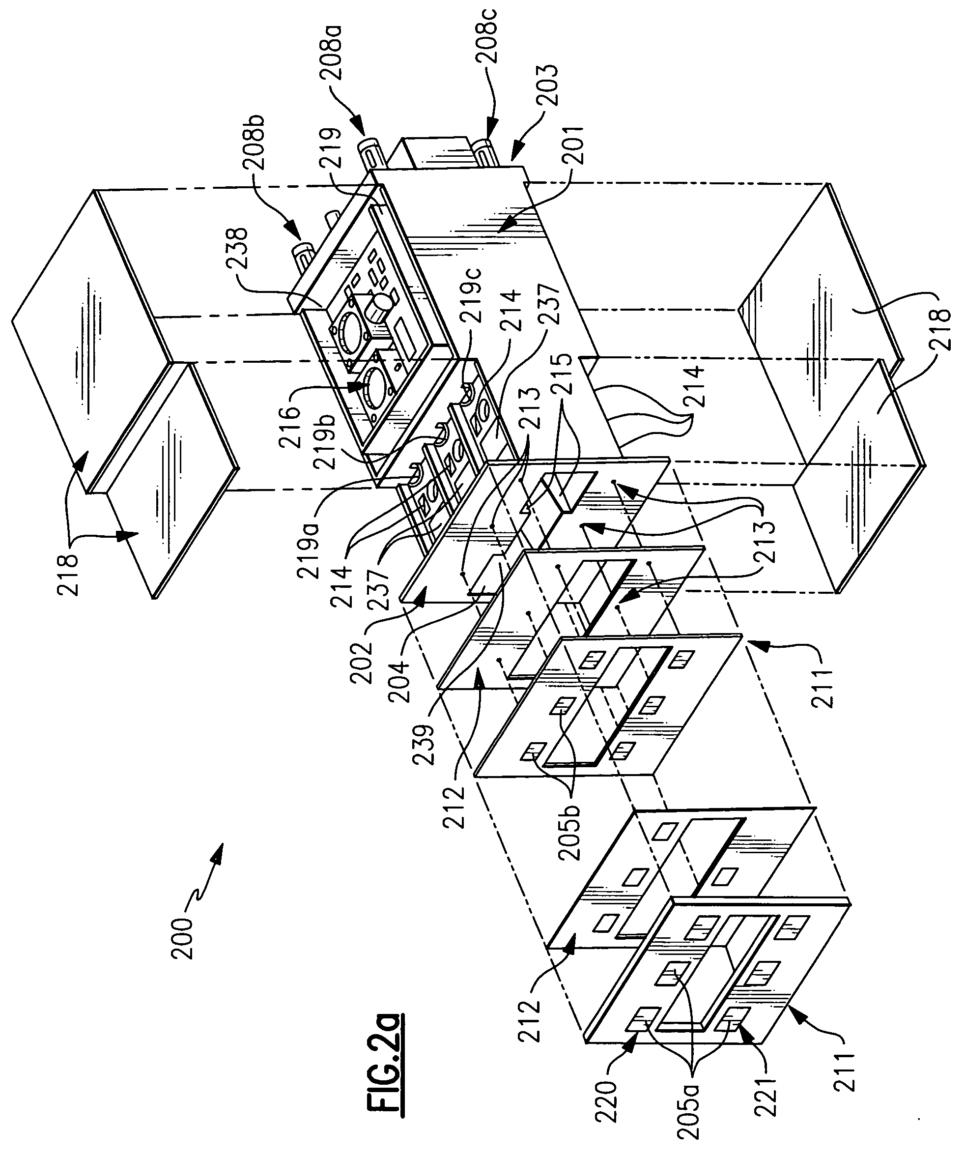
[0009] It is an object of the present invention to overcome the problems of the prior art by providing a compact, lightweight line-replaceable transmit / receive (T / R) unit for assembling active phased array antenna systems that provide operation in two distinct frequency bands. The line-replaceable T / R unit in accordance with the present invention integrates the radiating elements and their transmit / receive electronics plus the associated DC power supply and control circuitry into a compact, lightweight modular building block for assembling multi-band active phased arrays. The units are constructed using light weight materials having favorable thermal properties. The line-replaceable T / R unit employs air cooling to convectively remove heat from the active electronics where the radiating element waveguide design for one operating frequency band also serves as an air coolant passage. The line-replaceable T / R unit is designed to plug into an array structure, in a manner that promotes ready access for service or replacement as required. This approach also facilitates system growth by either increasing the array size through additional line-replaceable T / R units or by upgrading the line-replaceable T / R units with, for example, higher power transmit amplifiers. The line-replaceable T / R unit is described herein in the context of a dual-band application where the line-replaceable T / R units, when assembled into an antenna array structure, form an active phased array antenna capable of operating on two distinct frequency bands with uncompromised performance.

Problems solved by technology

Juxtaposing multiple single-band array antennas to achieve operation in more than a single frequency band is incompatible with platform limitations, particularly from a size viewpoint.
These designs exhibit low efficiencies at the lower operating frequency and lose full control of the beam at the upper frequency extreme.
The drawback with these designs is that the amplifiers exhibit non-optimum performance due to their necessity to cover an extended bandwidth.
Additionally, the quantity of elements and electronics is denser than what would generally be required for the lower frequency band, which leads to the array being heavier, having higher heat densities, and being too costly.
Most host platform limitations, especially mobile platforms, necessitate that the radar system be assembled with light weight, small volume components and structures.
To date, no such radar systems are available.

Method used


Image

  • Line-replaceable transmit/receive unit for multi-band active arrays
  • Line-replaceable transmit/receive unit for multi-band active arrays
  • Line-replaceable transmit/receive unit for multi-band active arrays

Examples


Embodiment Construction

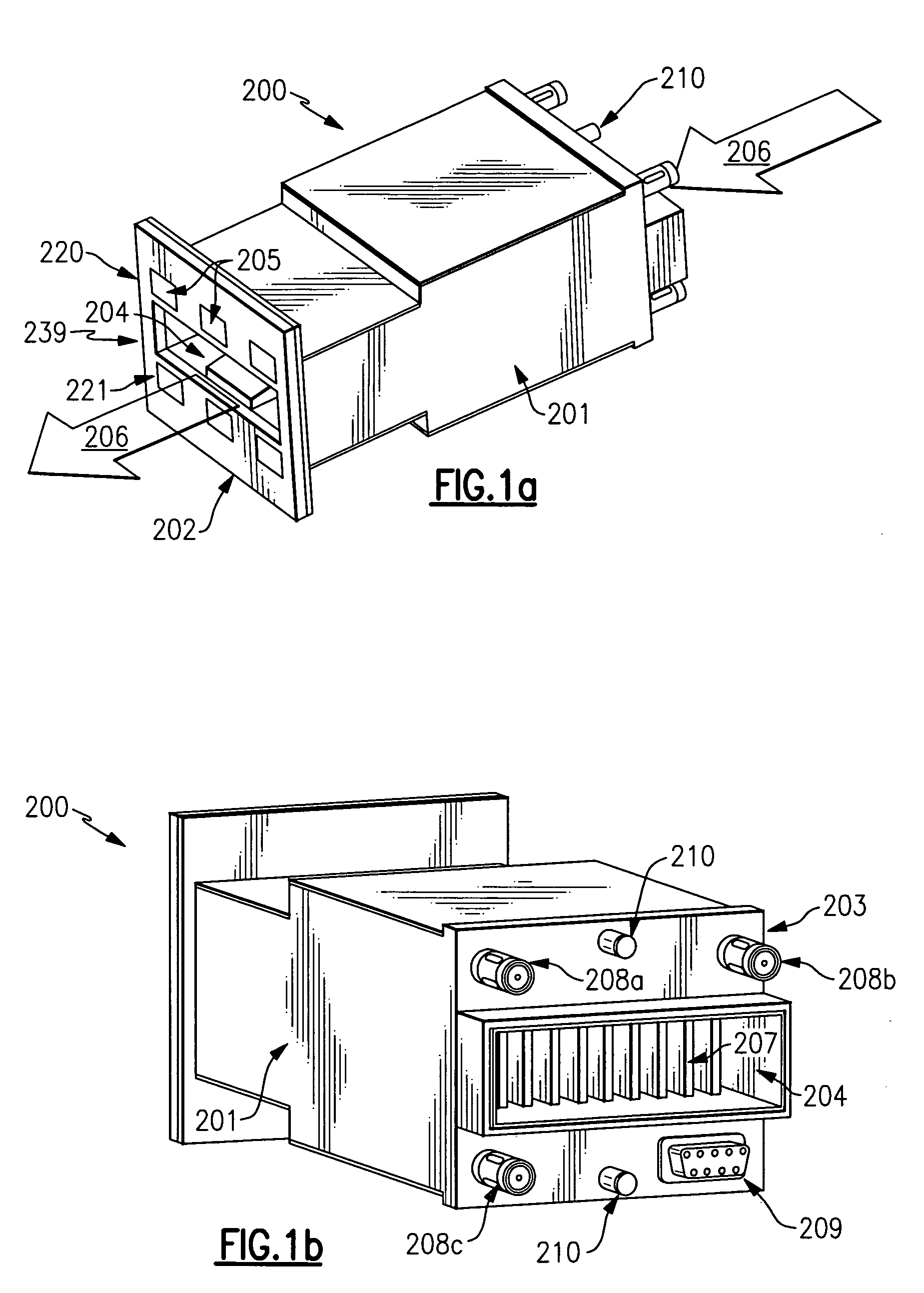
[0029] One embodiment of the present invention will now be explained with reference to FIG. 1a and FIG. 1b. FIG. 1a is a perspective front view and FIG. 1b is a perspective rear view of a line-replaceable transmit / receive (T / R) unit for a phased array antenna in accordance with one embodiment of the present invention. The housing 201 of line-replaceable T / R unit 200 is fabricated as a one-piece, net-shape casting, for example, which requires minimal, if any, machining and provides thin cross-sections resulting in a low overall weight. Housing 201 can be made from a variety of well-known materials, one example of which is a metal matrix composite, preferably Aluminum Silicon Carbide (AlSiC). AlSiC has a high thermal conductivity to promote heat extraction from heat producing components, and has a thermal coefficient of expansion well matched to the typical component materials, which results in reduced stresses during temperature cycling. Additionally, AlSiC is electrically conductive...


PUM


Abstract

A line-replaceable unit for a phased array antenna including a thermally conductive housing having a front face and an opposed rear face, at least one open-ended waveguide extending through the housing from the front face to the rear face, at least one first radiating element including the waveguide and adapted to emit energy in a first frequency band; and at least one second radiating element positioned on the front face of the housing and adapted to emit energy in a second frequency band distinct from the first frequency band. The waveguide is dimensioned to pass energy in the first frequency band and is exposed to the environment outside the housing at the front and rear faces to define a cooling duct passing through the housing.

Description

CROSS REFERENCE TO RELATED APPLICATION [0001] This application claims the benefit under 35 U.S.C. §119(e) of U.S. Provisional Application Ser. No. 60 / 571,710, filed May 17, 2004, the entirety of which is incorporated herein by reference.FEDERAL RESEARCH STATEMENT [0002] This invention was made with government support under M67854-04-C-2004 awarded by the United States Marine Corps. The government has certain rights in the invention.FIELD OF THE INVENTION [0003] The present invention generally relates to array antenna systems, and more particularly, line-replaceable transmit / receive units for multi-band active phased array systems with forced air cooling. BACKGROUND OF THE INVENTION [0004] Next generation radar systems will be required to perform multiple missions and deliver higher levels of performance, while being readily integrated into their host platforms. Providing the ability for the radar system to operate in more than a single frequency band enables realizing optimum multi-...

Claims


Application Information

Patent Timeline
Patent Type & Authority Applications(United States)
IPC IPC(8): H01Q1/02H01Q3/36H01Q5/00H01Q5/40H01Q5/42H01Q21/00H01Q21/06H01Q21/28
CPCH01Q1/02H01Q3/36H01Q13/0275H01Q21/0025H01Q5/42H01Q21/064H01Q21/065H01Q21/28H01Q5/40H01Q21/0087
Inventor EDWARD, BRIAN J.MARZIALE, JOHN M.RUZICKA, PETER J.
Owner SAAB INC
Learn More