
Unitized membrane electrode assembly and process for its preparation

Inactive Publication Date: 2005-11-17
EI DU PONT DE NEMOURS & CO
View PDF7 Cites 29 Cited by
  • Summary
  • Abstract
  • Description
  • Claims
  • Application Information

AI Technical Summary

Problems solved by technology

In this process, stray fibers from the electrically conductive electrode material may bridge across the thin membrane, interconnecting the electrodes that could result in short-circuiting in an operating fuel cell.
However, in MEA fabrication, this poses a problem because the membrane and the electrode layers have to be cut separately resulting in a slow-down of the manufacturing process and loss of productivity.
In this case, a rejected or scrapped piece cannot be ground up and remolded.
The chemical nature of thermosetting materials may lead to undesirable process and product attributes in the fuel cell application.
Such materials often require a relatively long time period for chemical reaction to solidify them; they are commonly used for low-volume parts manufacture, where fast cycle times are not important.
Reacting components in thermosetting materials may generate undesirable gaseous emissions, requiring forced ventilation of the production area, raising environmental issues, and forming bubbles in the solidified part.
The chemical nature and reactivity of residual low-molecular-weight components in thermosetting materials present the possibility of contamination of the membrane or catalyst in a fuel cell.
Further, unreacted chemical functional groups in the thermosetting materials provide likely sites for corrosion or other attack by the acidic species in the fuel cell environment.
A further deficiency of thermosetting materials, as implied in the description above, is the inability to repair or recycle a defective part.
Such a problem can significantly hurt the economics of manufacture, as the yield loss of the valuable MEA contributes strongly to manufacturing cost.
Physical properties of thermosetting materials are also often insufficient for durable fuel cell operation.
Many lack mechanical toughness, and low-modulus forms such as natural rubber require very precise control of stack pressure to assure the desired MEA thickness when assembled.
Finally, the processing of curable resins introduces difficulties in fabrication of the unitized MEA.
The relatively low viscosity of the uncured material makes it difficult to control and limit its flow into the porous diffusion backings.
Excessive flow can seal off part of the expensive catalyst layers, rendering it inactive.

Method used


Image

  • Unitized membrane electrode assembly and process for its preparation
  • Unitized membrane electrode assembly and process for its preparation
  • Unitized membrane electrode assembly and process for its preparation

Examples


example 1

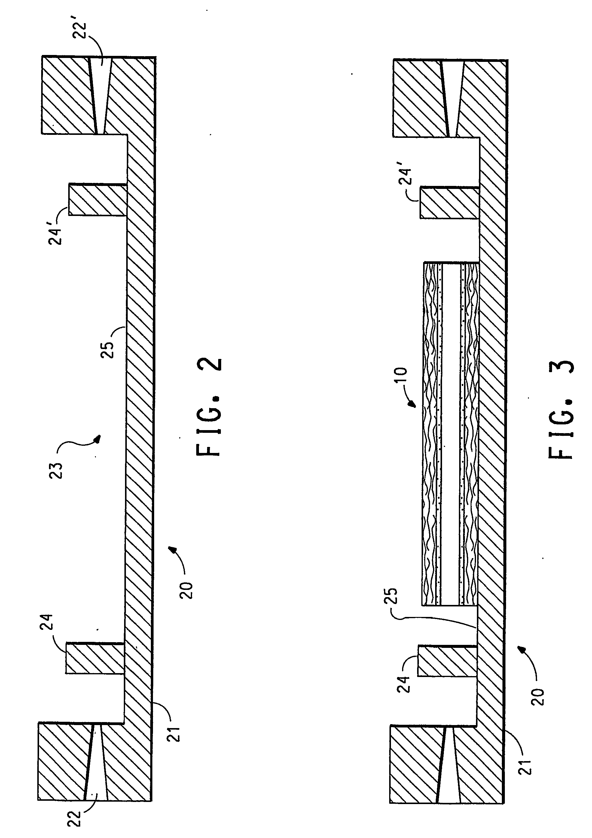
[0085] A two-part injection-molding tool was fabricated for encapsulation molding of a membrane electrode assembly (MEA) for a PEM fuel cell. The tool was designed to form a cavity with a peripheral frame about 0.18 mm thick and 7.6 cm in diameter, enveloping a square central area about 0.07 mm thick and 51 cm in diameter. Two gates were placed in the center of two opposite edges of the frame.

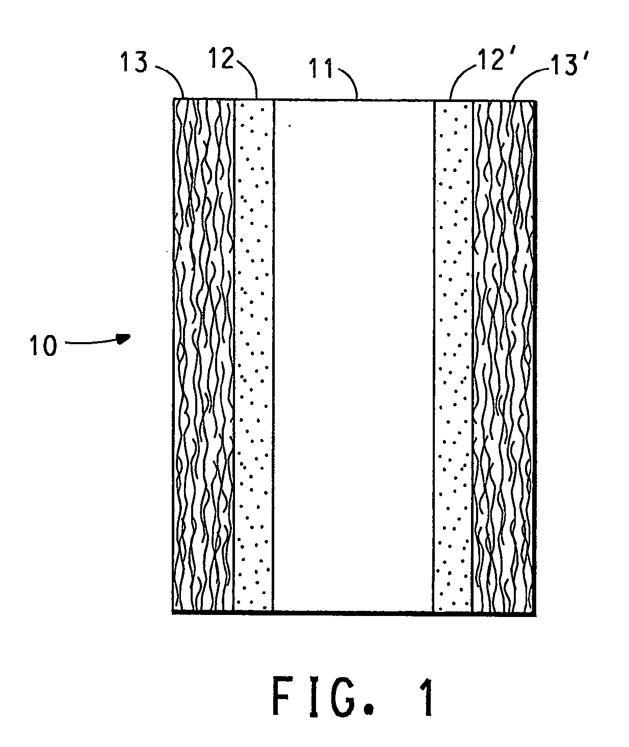
[0086] A three-layer sandwich comprising 0.2-mm-thick Nafion® 117, manufactured by DuPont, Wilmington, Del., between two layers of a carbon-fiber-based diffusion backing, “Sigracet” GDL 10BB manufactured by SGL Carbon Group, Meitingen, Germany, each 0.036 mm thick in their uncompressed state, was placed in the square central area of the molding tool. This sandwich was in essence a “dummy” MEA, in that it only lacked the electrocatalysts necessary for fuel cell function, but could serve mechanically and electrically to work in the same way.

[0087] All layers of the sandwich were cut to the same...

example 2

[0089] A unitized MEA was prepared using the tool and process described in Example 1 with the following exception: The dummy MEA sandwich was cut to be about 1 cm smaller than the square central area of the tool, such that the components did not extend as far as the thicker frame area. This change assured that all components of the MEA were supported within the closed tool, addressing the problem seen in Example 1.

[0090] Although the injected polymer was thus geometrically unable to fully encapsulate the edges of the MEA sandwich by flowing above and below it, it appeared to enter the sandwich through the edges at all points. The sandwich components were again found to be held together by the thermoplastic polymer seal thus formed. The membrane was not visible anywhere around the sample, indicating that the polymer was able to contact both diffusion backings all around the sandwich, holding them in place. The frame area being thicker than the area in which the MEA sandwich was supp...

example 3

[0092] Example 2 was repeated with the following exception: The membrane in the dummy MEA sandwich was cut to be about 0.2 cm larger than the diffusion backings, such that it extended beyond them all around their perimeter.

[0093] The sandwich components were held together by the thermoplastic polymer seal thus formed, and it would be expected to have no short-circuiting between the anode and cathode diffusion backings. However, the membrane was not fully encapsulated at its edges, rather it was pushed either against the upper or lower tool face by the in-flowing thermoplastic polymer. The edge of the membrane was visible around nearly the entire specimen, as the thermoplastic polymer was unable to contact one of the diffusion backing layers at these points.

[0094] To remedy this problem, supporting structures, such as ribs or domes, may be built into both the top and bottom tool parts around the MEA sandwich. These structures are positioned to pinch the edge of the membrane that ex...


PUM

PropertyMeasurementUnit
Electrical conductivityaaaaaaaaaa
Sizeaaaaaaaaaa
Volumeaaaaaaaaaa

Abstract

The invention provides a unitized membrane electrode assembly having a first gas diffusion backing having sealing edges; a polymer membrane; a second gas diffusion backing having sealing edges; a first electrocatalyst coating composition present at the interface of the first gas diffusion backing and the polymer membrane; a second electrocatalyst coating composition present at the interface of the second gas diffusion backing and the polymer membrane; and a thermoplastic polymer, fluid impermeable, seal, wherein the thermoplastic polymer is impregnated into the sealing edges of the first and second gas diffusion backings, and the seal envelops a peripheral region of both the first and second gas diffusion backings and the polymer membrane.

Description

FIELD OF THE INVENTION [0001] This invention relates to a membrane electrode assembly for use in electrochemical cells and more particularly to thermoplastic, fluid impermeable seals for the membrane electrode assembly. Further, the invention relates to a process for preparing unitized membrane electrode assemblies providing high productivity. BACKGROUND OF THE INVENTION [0002] A variety of electrochemical cells falls within a category of cells often referred to as solid polymer electrolyte (“SPE”) cells. An SPE cell typically employs a membrane of a cation exchange polymer that serves as a physical separator between the anode and cathode while also serving as an electrolyte. SPE cells can be operated as electrolytic cells for the production of electrochemical products or they may be operated as fuel cells. [0003] Fuel cells are electrochemical cells that convert reactants, namely fuel and oxidant fluid streams, to generate electric power and reaction products. A broad range of reac...

Claims


Application Information

Patent Timeline
IPC IPC(8): H01M4/86H01M4/88H01M4/94H01M4/96H01M8/02H01M8/10H01M8/24
CPCH01M4/8605H01M4/881H01M4/96H01M8/0271Y02E60/521H01M8/0286H01M8/1002H01M8/1004H01M8/242H01M8/0273H01M8/1007Y02E60/50H01M4/86H01M8/02H01M8/2483
Inventor LERTOLA, JAMES GERARD
Owner EI DU PONT DE NEMOURS & CO
Learn More