
Method for producing heated components for injection moulding apparatus and heating equipment in general

a technology of heating equipment and injection moulding apparatus, which is applied in the direction of electric devices, electrochemical generators, domestic applications, etc., can solve the problems of significant droplet deformation or impact on a surface, adversely affecting the dielectric properties of an insulating coating, and heating heater type operating inefficiently, etc., to achieve simple and cost-effective effects

Inactive Publication Date: 2005-11-24
INGLASS SRL
View PDF3 Cites 26 Cited by
  • Summary
  • Abstract
  • Description
  • Claims
  • Application Information

AI Technical Summary

Benefits of technology

[0016] The object of the present invention is to provide a simple and cost effective method for applying heating resistors to components for injection moulding apparatus, and in general for heating equipment, by “Thermal Spray” technology.
[0017] An additional object of the invention is to allow the production of heating resistors directly on components for injection moulding apparatus to operate at temperatures up to 500° C., by means of the use, one of the Thermal Spray technologies, i.e. the most appropriate according to the material to be sprayed, resulting in improved reliability and greater efficiency in terms of reduced mass and energy consumption.
[0018] Another object of the invention is to do without thermocouples for the control of the heaters by means of heating materials with large temperature coefficient of resistance, resulting in simpler layout for the related electrical circuits with improved reliability.
[0019] A further reduction of energy losses is achieved with a dielectric layer deposited on the heater, and having low emissivity for infrared radiation in such a way to take the dispersion of thermal energy at the minimum level.

Problems solved by technology

However this type of heater operates inefficiently because of its small capability to transfer heat energy while developing high temperature difference.
The high particle temperatures and speeds achieved results in significant droplet deformation or impact on a surface, producing layers made of “splats” that conform and adhere to the substrate surface.
Porosity may be beneficial in tribological applications and in thermal barrier coatings but, on the contrary, may adversely affect the dielectric properties of an insulating coating.
This prior art, however, is not in practice usable in itself in the applications provided for the present invention, essentially because it not allows sufficient reliability or proper operation for systems whose working temperature has to reach values up to 500° C. Moreover, the prior art gives rise to problems connected to hot corrosion, corrosion in wet environments and salt fog, risk of cracks and excessive porosities in the dielectric layers with consequent failures of the heating resistors, as well as difficulties in obtaining reliable electrical connections.

Method used


Image

  • Method for producing heated components for injection moulding apparatus and heating equipment in general
  • Method for producing heated components for injection moulding apparatus and heating equipment in general
  • Method for producing heated components for injection moulding apparatus and heating equipment in general

Examples


Embodiment Construction

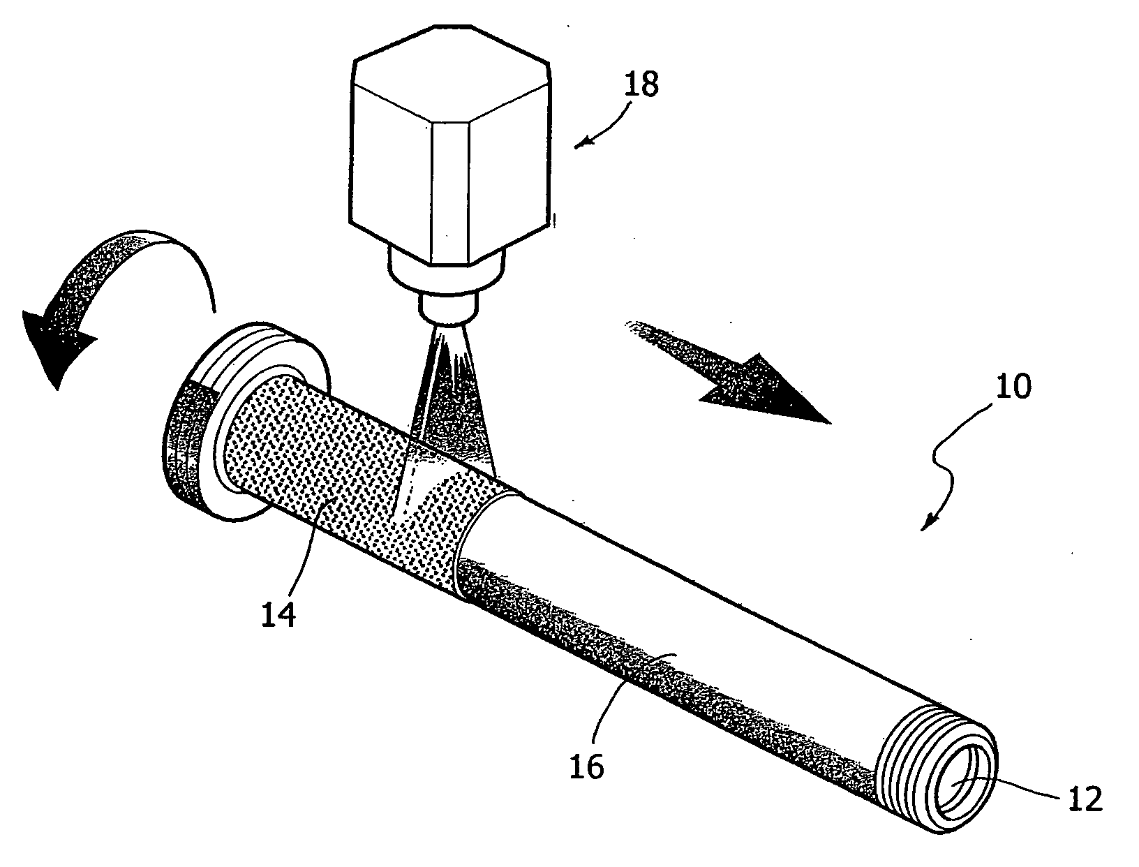
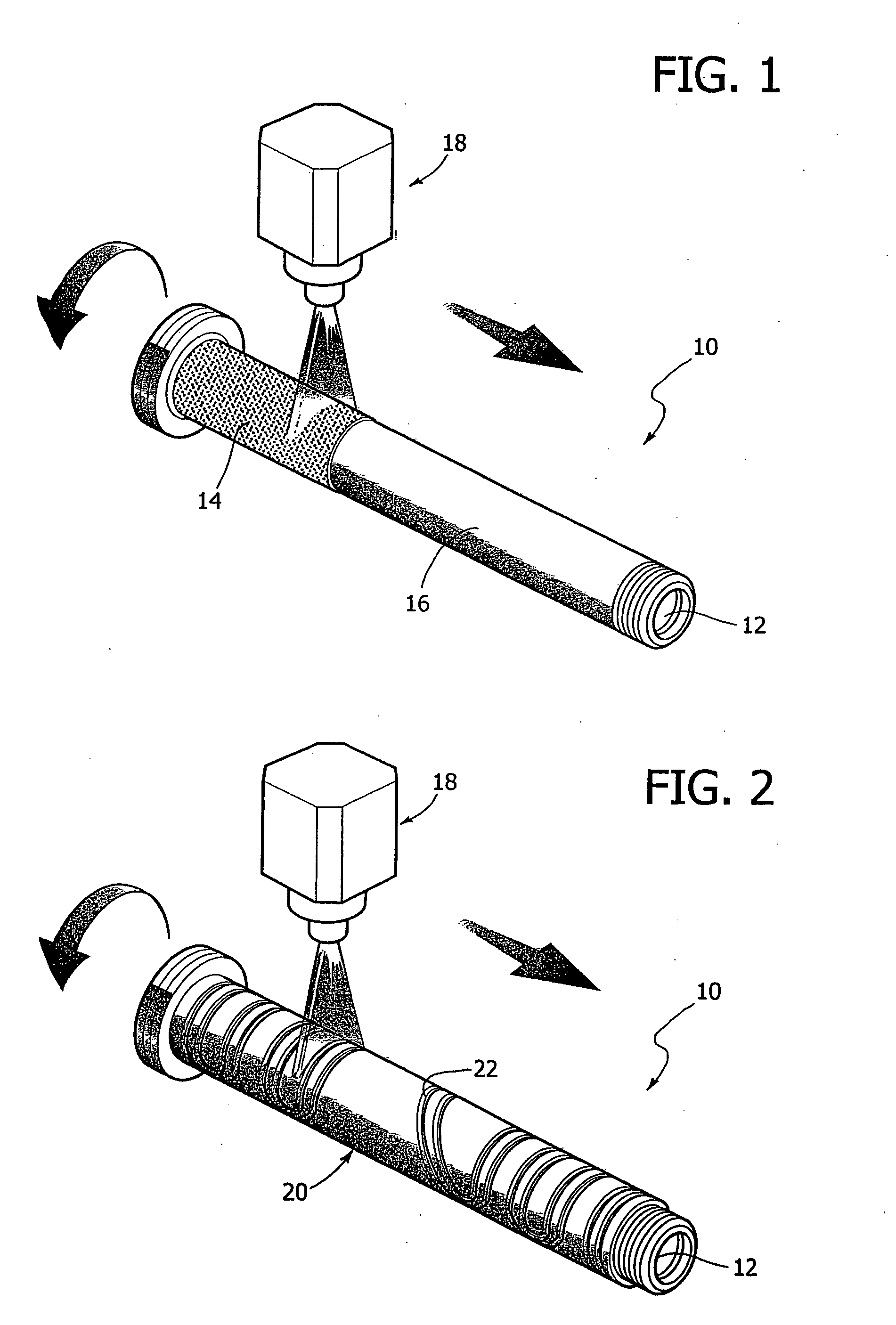
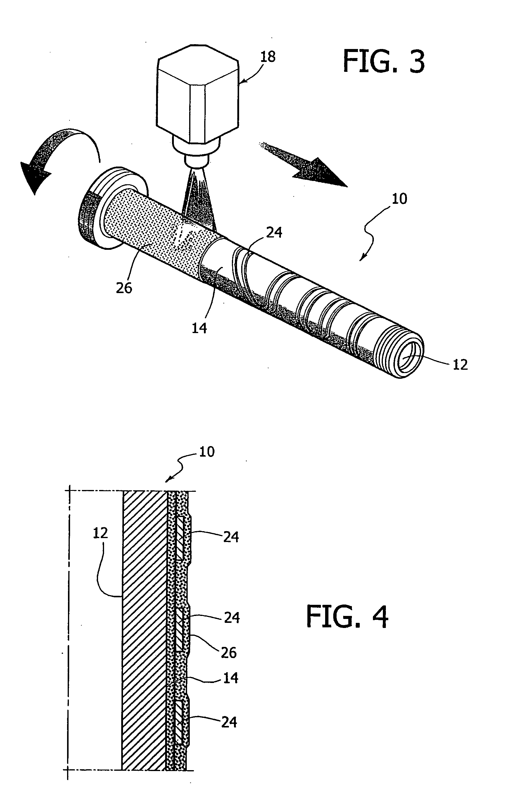
[0027] With reference to FIGS. 1 through 3, the sequence of processes used for implementing the method shall now be described for a heating element on the outer surface of a cylindrical body 10 provided with a channel 12 for the passage of material to be injected.

[0028] In this example, the body 10 is machined to have a core with a passageway formed therein for the communication of the flowable material such as in a nozzle for injection moulding of plastic materials. However, it is to be understood that the described method is by no means limited to circular cylinders or tubes but it can be extended for the production to any other component with other shapes with special interest to other components of an injection moulding system where heaters are required such as hot chambers, heating plates, injection nozzles, extensions and hot channels of various kinds as well as to the related electrical connections. In addition, experts can conceive application of the same method for the rea...


PUM

PropertyMeasurementUnit
Temperatureaaaaaaaaaa
Pressureaaaaaaaaaa
Electrical conductivityaaaaaaaaaa

Abstract

A method for producing components for injection moulding comprising a body made of thermally conducting material with expansion coefficient matching that of the insulating layers and provided with a passage for the material to be injected. At least one strip of electrically conducting material with high change of resistance with temperature, forming a heating resistor or inductor is applied on a electrically insulating base layer previously directly applied on the body. At least one final insulating layer with low thermal emissivity is then applied to optimise electrical efficiency. The method utilises thermal spray techniques and can be applied also for production of other heating equipment.

Description

FIELD OF THE INVENTION [0001] The present invention relates to a method and processes of producing components for injection moulding apparatus. [0002] The present invention was developed with specific reference to the production of heated components for injection moulding apparatus including a body made of thermally conducting material provided with at least one conduit for the passage of material to be injected and at least one heating electrical resistor applied directly on the body to reach temperatures up to 500° C. [0003] Other components for injection moulding equipment comprising a body made of thermally conductor material wherein a heating resistor is applied are, for example, hot chambers, heating plates, injection nozzles (as generally described in the documents U.S. Pat. No. 6,609,902, U.S. Pat. No. 6,555,044 and US-2003 / 0003188) and hot channels in general. Other components whereto the invention also finds application can include accessories of injection moulding apparat...

Claims


Application Information

Patent Timeline
IPC IPC(8): B29C45/20B29C45/27B29C45/30B29C45/78C23C28/00H01C3/20H01M6/00
CPCB29C45/2737B29C45/2738B29C45/78B29C2045/2746C23C28/321C23C28/345Y10T29/49083H01C3/20Y10T29/49432Y10T29/49115Y10T29/49085Y10T29/49099Y10T29/49087C23C28/347
Inventor CIRRI, GIANFRANCOPRUDENZIATI, MARIA
Owner INGLASS SRL
Learn More