Electrophoretic assembly of electrochemical devices
a technology of electrochemical devices and electrochemical components, applied in the field of bipolar electrochemical devices, can solve the problems of limiting the available shape of batteries, affecting the performance of electrochemical devices, and the act of electrophoresis not by itself creating complete devices, etc., to achieve the effect of improving performance results, poor volumetric utilization of space, and relatively low energy density of such batteries
- Summary
- Abstract
- Description
- Claims
- Application Information
AI Technical Summary
Benefits of technology
Problems solved by technology
Method used
Image
Examples
example 1
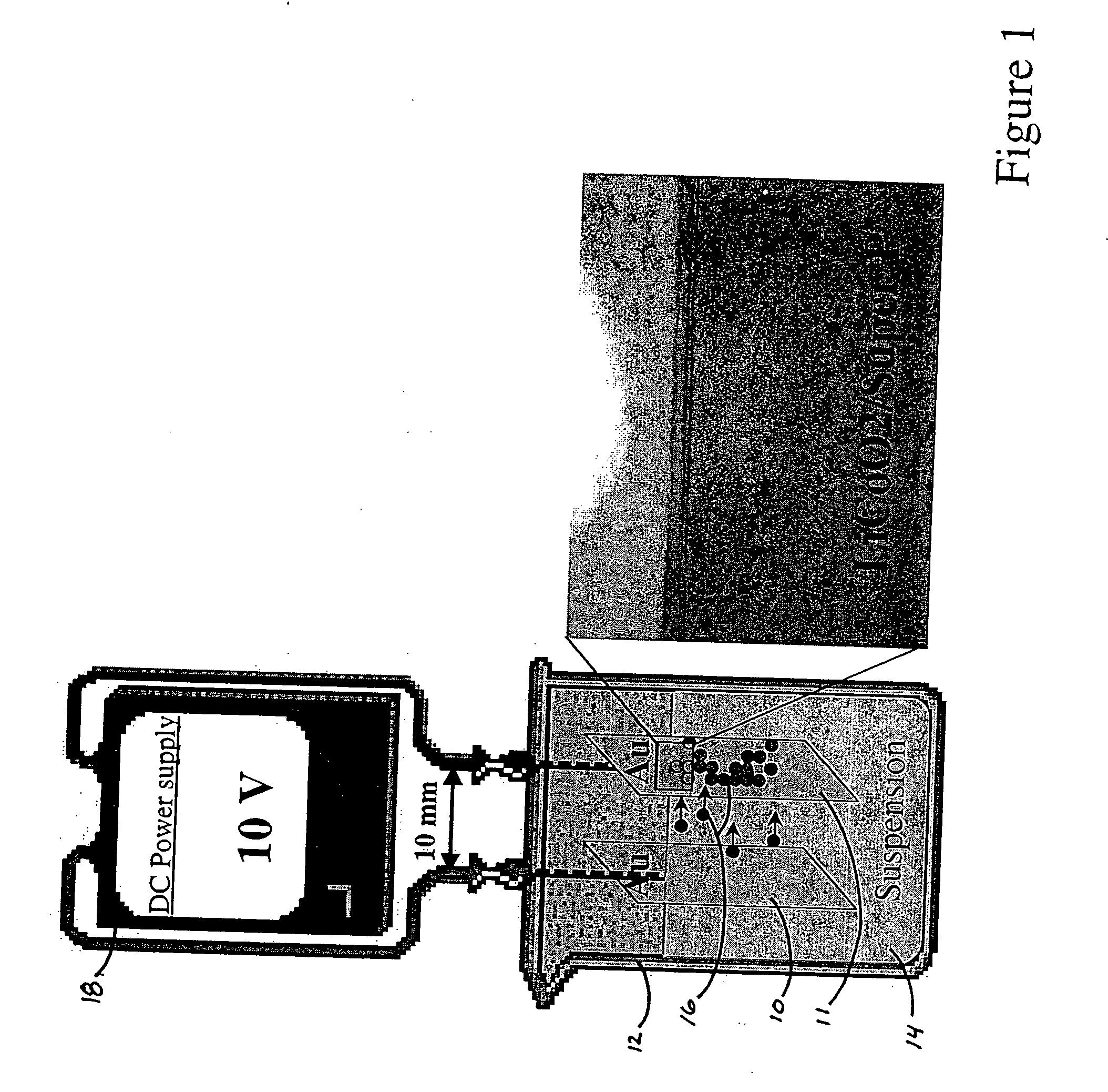
[0073] The direction of electrophoretic migration was determined for several materials and solvent systems useful in batteries as follows. Measurements were made of the direction of motion of powders suspended in solvents between two gold working electrodes under an applied voltage. The gold electrode configuration was one of the following: (1) as shown in FIG. 1, two parallel films of gold 10, 11 sputtered on glass placed ˜0.5 cm to ˜1 cm apart in a small glass beaker 12 (20 ml or 30 ml) in which the suspension 14 was placed, (2) two sputtered gold electrode films 1 cm apart in a glass plate with a shallow well within which the suspension was placed, or (3) as shown in FIG. 5, individually addressable gold microband electrodes 50 (ABTECH Scientific, Richmond, Va.) deposited on glass, typically of 20 micron width and 20 micron separation, onto which a suspension was placed. For the microband electrodes, the polarity alternated between bands.
[0074] A powder suspension was prepared b...
example 2
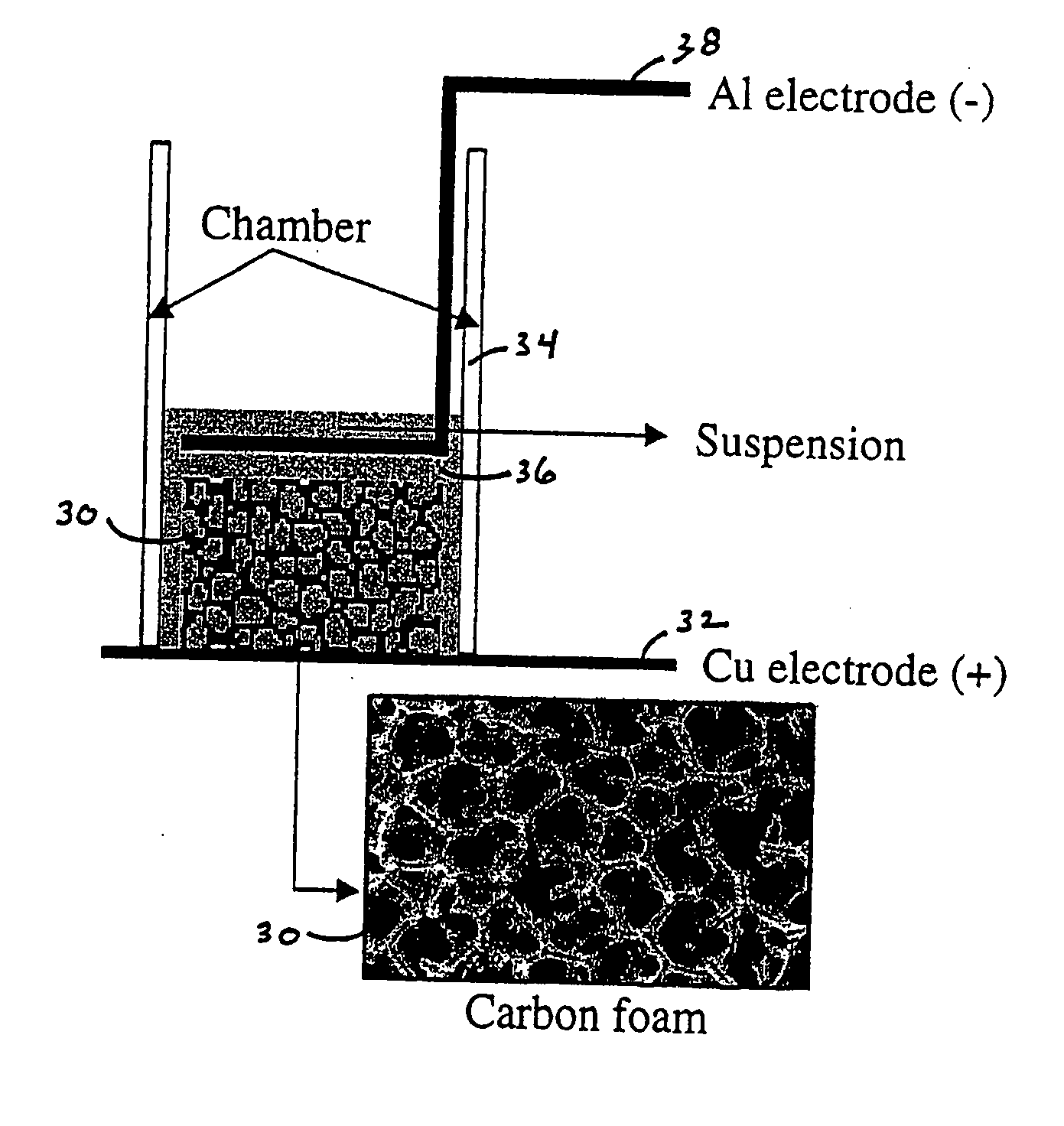
[0087] This example demonstrates the assembly of an electrochemical device using a continuous carbon structure having substantial open porosity, such as a carbon foam or carbon fiber mat, as one working electrode during electrophoretic processing. This porous electrode also becomes a working electrochemical storage electrode in the final device, which is a three-dimensional lithium ion battery.
[0088] In one series of experiments, reticulated carbon foams (Duocel™, ERG Materials and Aerospace, Oakland, Calif.) having pore dimensions of between 45 pores-per-inch (ppi) and 100 ppi were used. In some cases, the carbon foam was fired to high temperature (2300° C. to 2400° C.) in helium in order to improve the electrochemical storage capability. FIG. 6 shows a cyclic voltammetry scan of a heat treated carbon foam, tested in a Swagelok® cell against a lithium metal foil electrode, showing reversible electrochemical insertion of lithium at the expected potential for carbon anodes.
[0089] T...
example 3
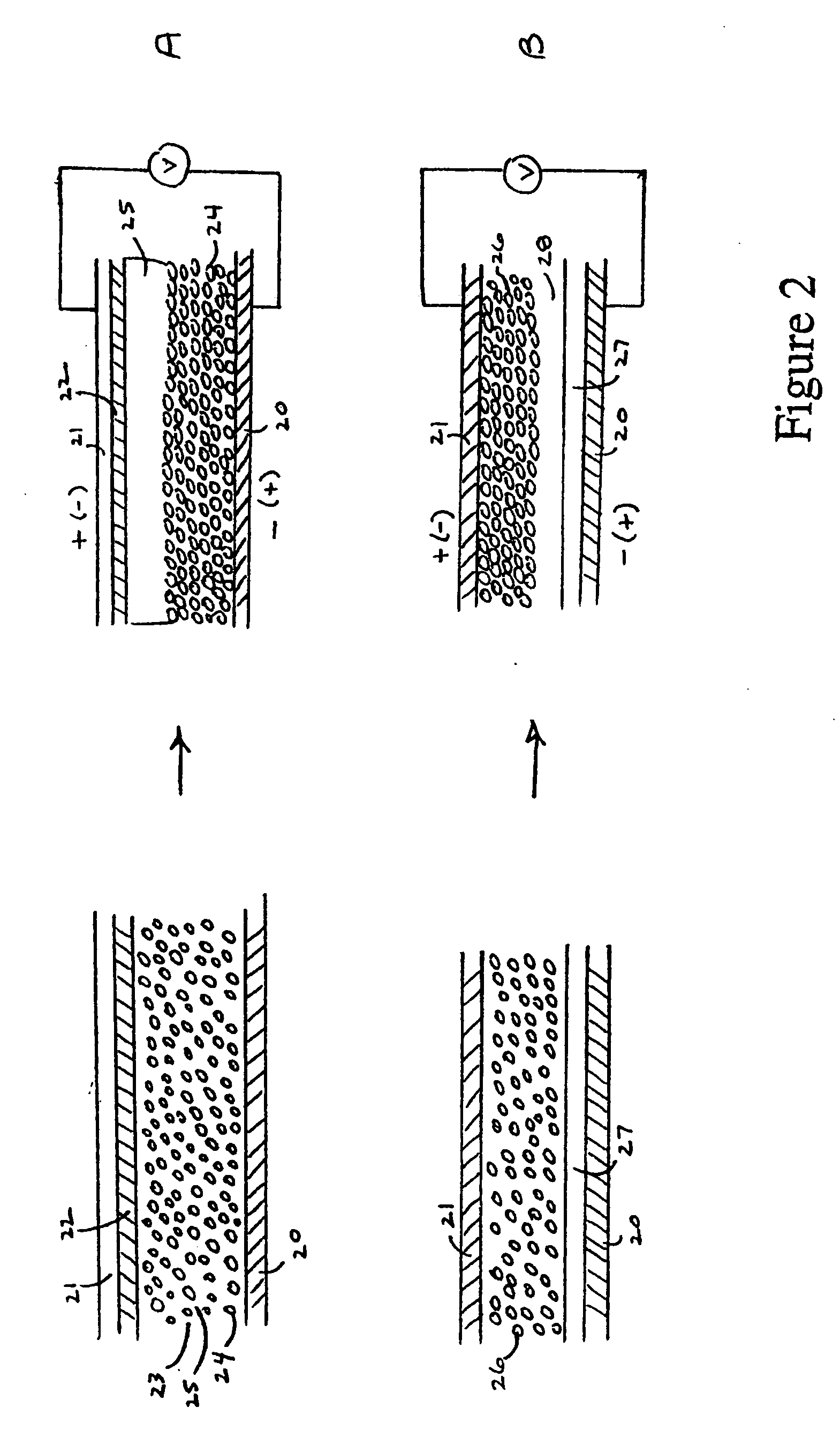
[0094] A two-dimensional electrophoretically separated device was fabricated using the following procedure. A 20 micron width microelectrode array 50 deposited on glass (ABTECH Scientific, Richmond, Va.) as shown in FIG. 5 was used. A suspension of LiCoO2 and Super P™ powder in acetonitrile, PEO 200,000, and LiClO4 was prepared using the same ratios as in Example 2, and the suspension was then further diluted with additional acetonitrile. The suspension was applied to the microelectrodes and a 1 volt potential difference was applied to the array. As shown in FIG. 8A, deposition of the LiCoO2 and Super P™80 at the negative electrodes 82 was observed, with no detectable deposition at the positive electrode 84.
[0095] Next, a suspension of MCMB in the same solvent mixture was applied, with the voltage being applied as shown in FIG. 8B. MCMB was found, like LiCoO2 and Super P™, to migrate to the negative electrode in this solvent mixture. Therefore, in order to deposit MCMB 86 at the op...
PUM
| Property | Measurement | Unit |
|---|---|---|
| volume | aaaaa | aaaaa |
| open circuit voltage | aaaaa | aaaaa |
| electronic conductivity | aaaaa | aaaaa |
Abstract
Description
Claims
Application Information
 - R&D
- Intellectual Property
- Life Sciences
- Materials
- Tech Scout
- Unparalleled Data Quality
- Higher Quality Content
- 60% Fewer Hallucinations
Browse by: Latest US Patents, China's latest patents, Technical Efficacy Thesaurus, Application Domain, Technology Topic, Popular Technical Reports.
© 2025 PatSnap. All rights reserved.Legal|Privacy policy|Modern Slavery Act Transparency Statement|Sitemap|About US| Contact US: help@patsnap.com


