Pollutant removal method and apparatus, and exposure method and apparatus

a technology of exposure method and apparatus, applied in the direction of optical radiation measurement, cleaning using liquids, instruments, etc., can solve the problems of uneven illuminance, decreased transmittance, and titanium oxide film beginning to be destroyed, so as to achieve the effect of quick removal of pollutants

Inactive Publication Date: 2005-12-15
NIKON CORP
View PDF15 Cites 83 Cited by
  • Summary
  • Abstract
  • Description
  • Claims
  • Application Information

AI Technical Summary

Benefits of technology

[0017] Taking the foregoing viewpoints into consideration, a first object of the present invention is to provide an exposure techniq...

Problems solved by technology

As a result, it is feared that the transmittance may be gradually decreased, and/or the uneven illuminance may appear.
Further, in the case of the use for a long period of time, the titanium oxide film begins to be destroyed, for example, due to the heat generated by the light absorption.
If the optical member in the projection optical system is exchanged, the following problems arise as well.
That is, the cost arises, which i...

Method used


Image

  • Pollutant removal method and apparatus, and exposure method and apparatus
  • Pollutant removal method and apparatus, and exposure method and apparatus
  • Pollutant removal method and apparatus, and exposure method and apparatus

Examples


first embodiment

of the Present Invention

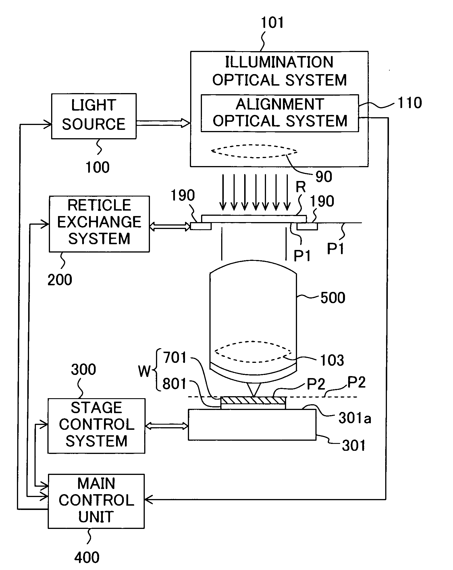
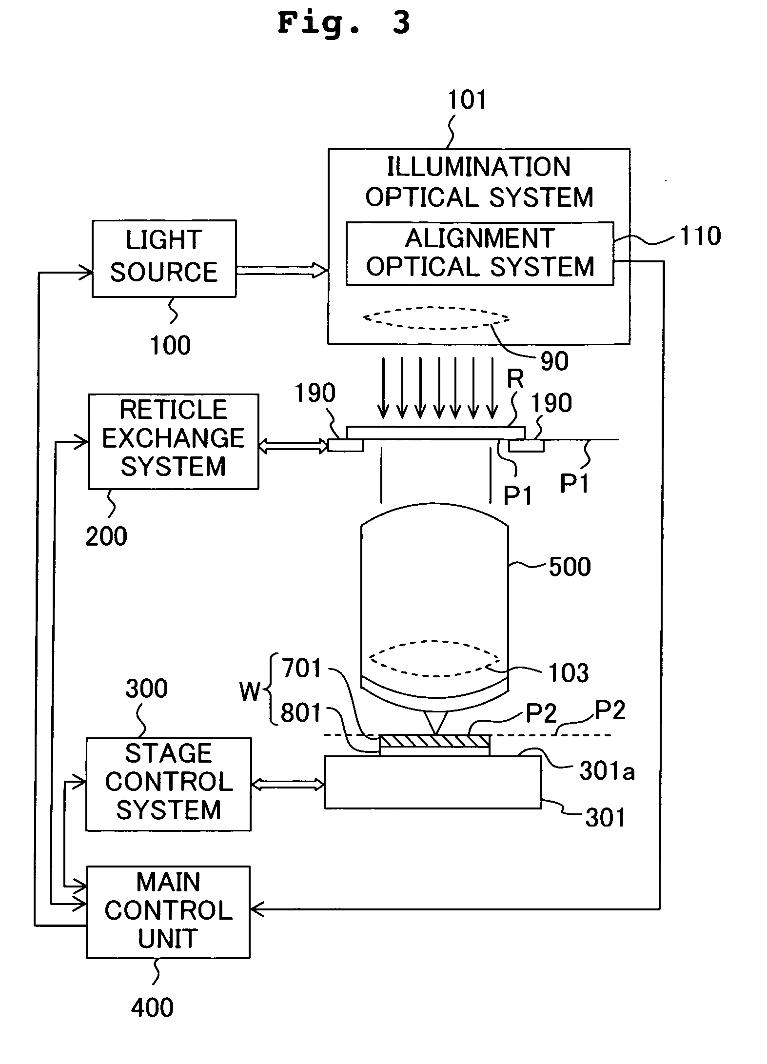
[0087] A first embodiment of the present invention will be explained below with reference to FIGS. 1 to 3.

example 1

[0088] In relation to a projection exposure apparatus based on the use of the ArF excimer laser, it is known that siloxane-based dirt components are decomposed and synthesized by the laser beam on the lens surface disposed most closely to the stage, and the silicon oxide film is deposited over a long period of time. The silicon oxide film is composed of pure SiO2, which is a deposit having no absorbance even in the deep ultraviolet region. However, if the silicon oxide film, which has a different refractive index, is deposited on the antireflection film, the reflection characteristic is deteriorated.

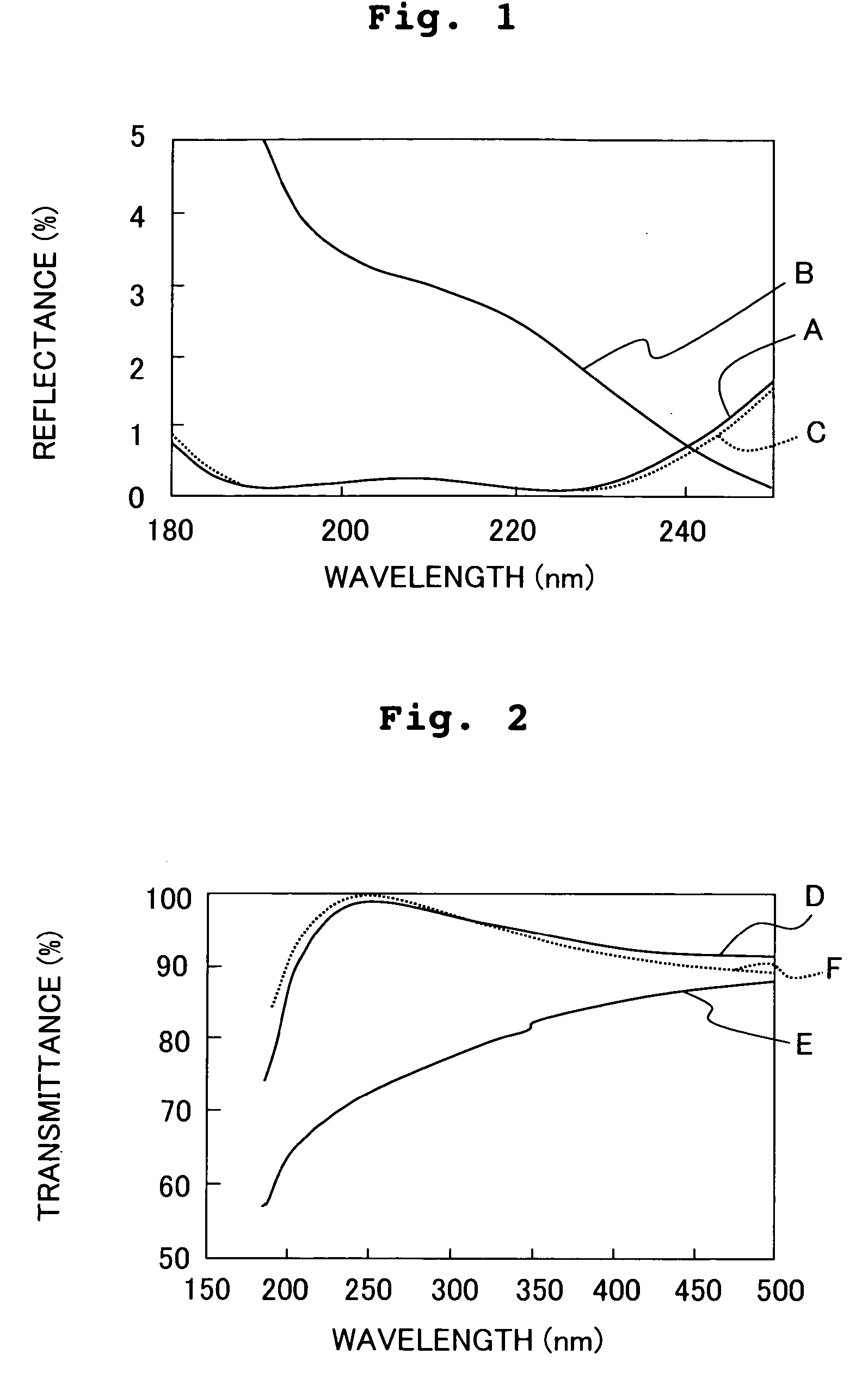
[0089]FIG. 1 shows the wavelength and the reflectance of the optical member. In FIG. 1, curves A, B, and C indicate the reflectance characteristics of an optical member A having a wide zone antireflection film (MgF2 / LaF3 / MgF2 / LaF3 / MgF2 / LaF3) applied onto a quartz substrate, a member B obtained by adhering the dirt on the optical member A, and a member C obtained by treating the member B...

example 2

[0095] However, the effect is insufficient in relation to the dirt when the pollutant includes organic substances such as hydrocarbon and inorganic substances such as ammonium sulfate. Accordingly, an etching solution (BOE / IPA) was prepared, which was obtained by mixing, at a ratio of 1:1, isopropyl alcohol and BOE obtained by mixing hydrofluoric acid (HF, 50% by weight) and ammonium fluoride (NH4F, 40% by weight) at a volume ratio of 1:10, for the following reason. That is, hydrocarbon is dissolved in isopropyl alcohol, ammonium sulfate is dissolved in water, and silicon oxide is dissolved in hydrofluoric acid. Therefore, when BOE / IPA is used as the etching solution, it is possible to quickly remove a variety of pollutants.

[0096] The dirt, which was actually generated in a relay unit (optical system) for carrying the excimer laser from a laser light source to a projection lens in a projection exposure apparatus based on the use of the KrF excimer laser, was tried to be removed wit...


PUM


Abstract

A method for quickly removing pollutants adhered to a predetermined optical member in an optical system. To remove the pollutants adhered to a lens (32A) disposed at the upper end of a projection optical system (PL), a cylindrical protecting member (53) is disposed through the openings in a reticle stage (22) and a reticle base (23). The bottom surface of a support section (56) at the tip section of a rod section (58) is brought into contact with the surface of the lens (32A) through the inner surface of the protecting member (53). A wiping cloth soaked with a washing solution containing hydrofluoric acid is attached to the bottom surface of the support section (56). The support section (56) is reciprocated via the rod section (58) to remove the pollutants on the lens (32A) with the wiping cloth.

Description

CROSS-REFERENCE [0001] This application is a Continuation Application of International Application No. PCT / JP03 / 014991 which was filed on Nov. 25, 2003 claiming the conventional priority of Japanese patent Application Nos. 2002-350944 filed on Dec. 3, 2002 and 2003-115098 filed on Apr. 18, 2003.BACKGROUND OF THE INVENTION [0002] 1. Field of the Invention [0003] The present invention relates to a pollutant removal technique for removing pollutants adhered to a surface of an optical member. In particular, the present invention is preferably usable to remove pollutants adhered to a surface of an optical member included in an illumination optical system or a projection optical system of a projection exposure apparatus which uses, for example, an excimer laser light source as an exposure light source. [0004] 2. Description of the Related Art [0005] In relation to members classified into optical members which are not limited to optical members for the projection exposure apparatus, the pr...

Claims


Application Information

Patent Timeline
IPC IPC(8): G02B27/00G03F7/20
CPCG02B27/0006G03F7/70916G03F7/70975G03F7/70941G03F7/70925B08B3/08G02B3/00G03F7/20G03F7/22
Inventor WATANABE, SHUNJIHAMATANI, MASATOKITAMOTO, TATSUYA
Owner NIKON CORP
Why Eureka
Try Eureka