Protective coating system for reflective optical elements, reflective optical element and method for the production thereof

a technology of reflective optical elements and protective coatings, applied in the field of protective coatings, can solve the problems of increasing operational costs, affecting the appearance of defects, and contamination by carbon-containing substances, and achieves the effects of improving the appearance quality, improving the service life, and improving the service li

Inactive Publication Date: 2005-12-15
CARL ZEISS SMT GMBH
View PDF7 Cites 30 Cited by
  • Summary
  • Abstract
  • Description
  • Claims
  • Application Information

AI Technical Summary

Benefits of technology

[0008] In a first aspect of the present invention, a protective coating system for reflective optical elements for the EUV and soft X-ray range is provided, with an upper coating system that comprises at least one uppermost layer made of one of the group consisting of an aluminum oxide, a beryllium aluminum oxide, a beryllium magnesium aluminum oxide, a titanium oxide, a magnesium oxide, a magnesium aluminum oxide, a manganese oxide, a nickel aluminum oxide, a sodium titanium oxide, an antimony oxide, a cerium titanium oxide, a cerium oxide, a strontium oxide, a zirconium oxide, a yttrium oxide, a rhodium oxide, a hafnium oxide, a ruthenium oxide, a boron oxide, a beryllium oxide, a calcium titanium oxide, a silicon nitri...

Problems solved by technology

These contaminations cause imaging defects.
These significantly increase the operational costs.
Contamination by carbon-containing substances does, however, still occur.
These cause uncontrolled reflectivity losses and wave front cha...

Method used


Image

  • Protective coating system for reflective optical elements, reflective optical element and method for the production thereof
  • Protective coating system for reflective optical elements, reflective optical element and method for the production thereof
  • Protective coating system for reflective optical elements, reflective optical element and method for the production thereof

Examples


example 1

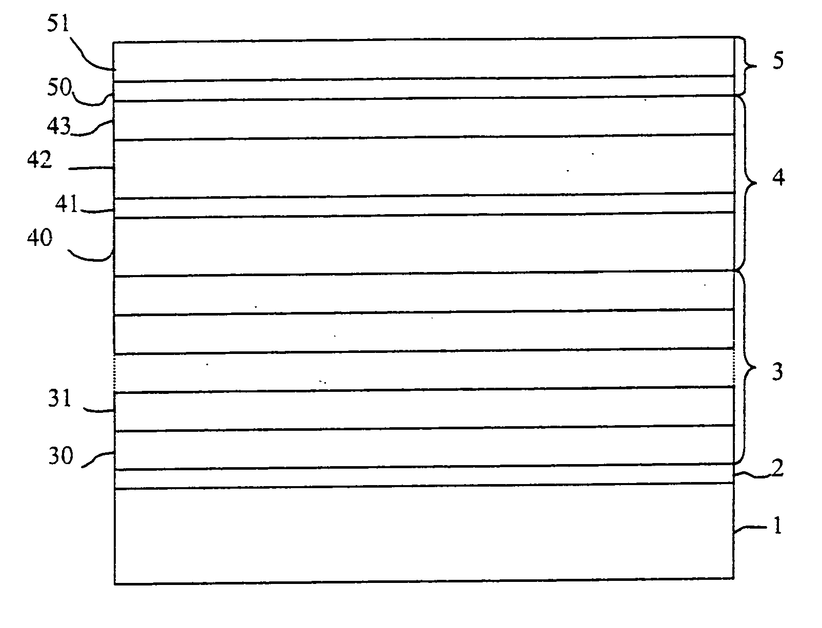
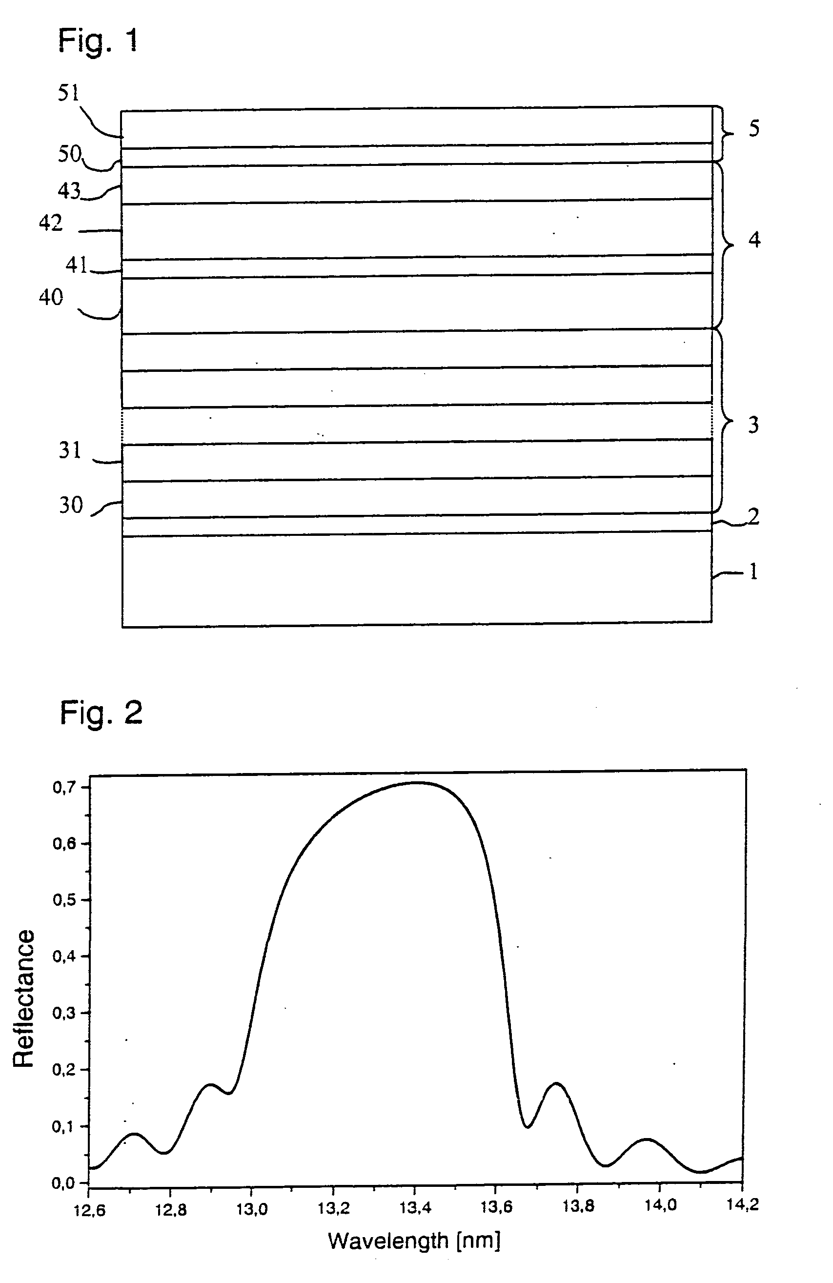
[0037] A multilayer of 50 periods of Mo (2.74 nm) / Si (4.11 nm) on an amorphous SiO2-substrate was provided with a protective coating system. This protective coating system comprises an upper protective coating system made of an aluminum oxide layer of a thickness of 1.29 nm and a lower coating system made of Rh2O3 (1.3 nm) / Y (1.5 nm) / amorphous C (1.35 nm) / Ce (1.11 nm). The rhodium oxide layer is the inert material layer, which assumes the function of an absorber. The yttrium layer, together with the cerium layer, corresponds to a spacer layer. The total thickness of yttrium and cerium is optimized for maximum reflectivity. The amorphous carbon layer serves as diffusion barrier. The yttrium layer and the cerium layer are also inert. At an angle of incidence of 0 degree to the surface normal and an operating wavelength of 13.4 nm under neglect of the surface- and interface roughness a maximum reflectivity of 70.3% (refer to FIG. 2) is obtained. Even after operation under residual gas ...

example 2

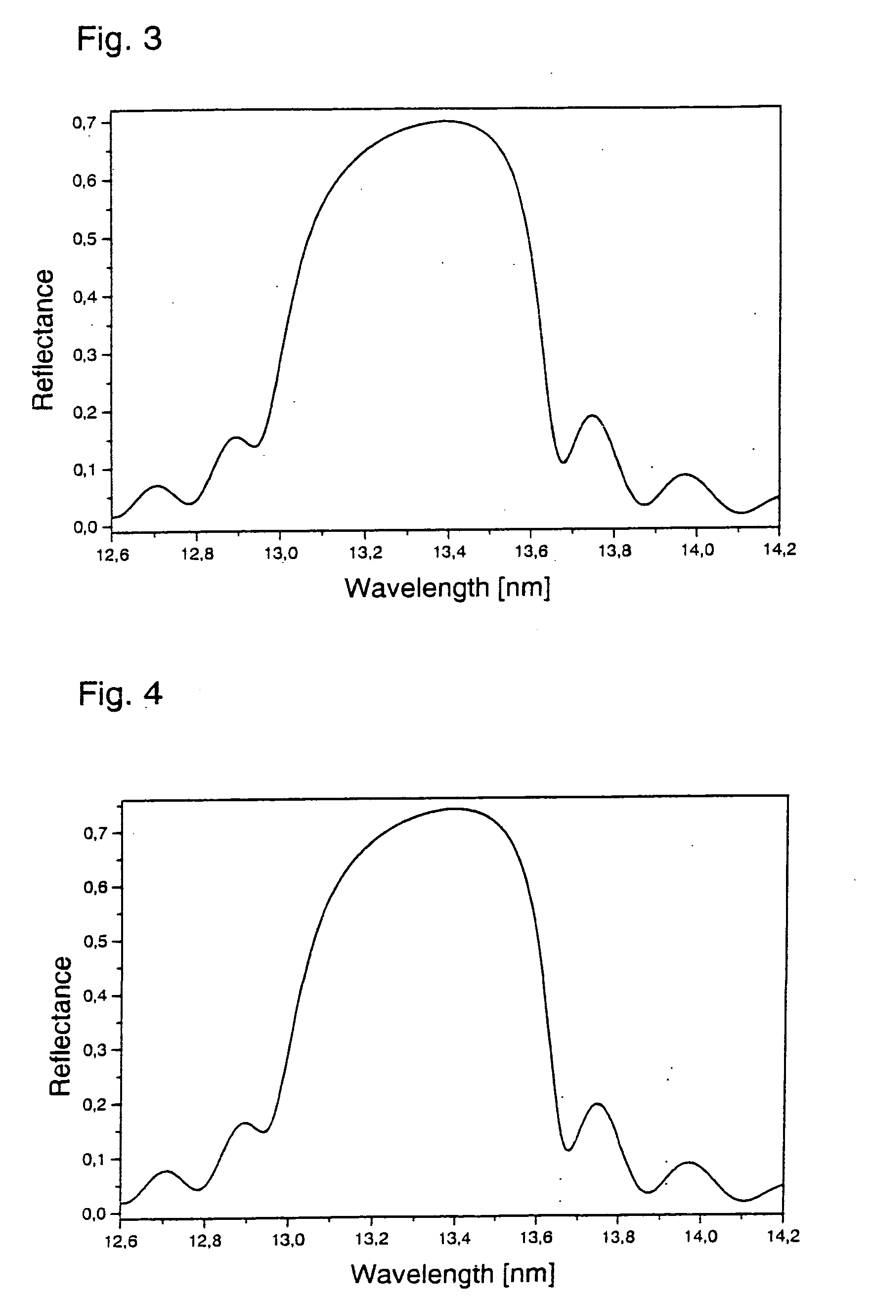
[0038] It concerns a multilayer of 50 periods of Mo (2.74 nm) / amorphous Si (4.11 nm) which is deposited on an amorphous SiO2-substrate. This multilayer shows an upper coating system of an Y2O3 (0.84 nm)-layer as carbon-growth poor material as well as a lower coating system of Y (3.36 nm) / Y2O3 (0.84 nm) / Y (3.36 nm) / Y2O3 (0.84 nm) / Y (3.36 nm). The Y2O3-layers suppress the growth of carbon-containing substances; the Y-layers are inert. The yttrium layers assume optically the function of a spacer, while the yttrium oxide layers assume the function of an absorber. At an angle of incidence of 0 degree to the surface normal and an operating wavelength of 13.4 nm under neglect of the surface- and interface roughness a reflectivity of 69.8% (refer to FIG. 3) is obtained. After irradiation for 65 hours under normal operating conditions the multilayer still shows a reflectivity of 97.0% of the initial reflectivity.

example 3

[0039] On a multilayer of 50 periods of Mo (2.74 nm) / amorphous Si (3.66 nm), which is deposited on an amorphous SiO2-substrate, is located a protective coating system consisting of an upper coating system of the one layer of Y2O3 (1.93 nm) as well as a lower coating system of the one layer of Y (3.58 nm), whereby the yttrium oxide layer shows a low adsorption rate for carbon-containing substances and is also inert. The yttrium layer has optically the function of a spacer, while the yttrium oxide layer assumes the function of an absorber. At an angle of incidence of 0 degree to the surface normal and an operating wavelength of 13.4 nm under neglect of the surface- and interface roughness a reflectivity of 73.3% (refer to FIG. 4) is obtained. After irradiation under normal operating conditions for 40 hours the multilayer still shows a reflectivity of 98.5% of the initial reflectivity.


PUM

PropertyMeasurementUnit
Fractionaaaaaaaaaa
Thicknessaaaaaaaaaa
Thicknessaaaaaaaaaa

Abstract

A limiting factor in the operation of EUV lithographic devices is the lifetime or the reflectivity of the reflective optics that is reduced by contamination with carbon-containing substances. Protective coatings that are resistant to oxidation or are inert against water are already known. According to the invention it is proposed to deposit protective coatings on, for example, multilayers that suppress the growth of carbon-containing substances in combination with layers that are inert against residual gas atmosphere and energy input. Even with a long operating time a high reflectivity is thereby retained. The protective coatings may be deposited by electron-beam vaporization, magnetron- or ion-beam sputtering.

Description

FIELD OF THE INVENTION [0001] The invention relates to a protective coating system for reflective optical elements for the EUV and soft X-ray wavelength range. In addition, the invention relates to a reflective optical element for the EUV and soft X-ray wavelength range. Furthermore, the invention relates to a method for the production of a reflective optical element for the EUV and soft X-ray wavelength range and a method for the production of a protective coating system. BACKGROUND AND PRIOR ART [0002] Reflective optical elements for the EUV and soft X-ray wavelength range may, for example, be multilayers. Multilayers are assembled from periodical repetitions, whereby in the simplest case one period consists of two layers. One layer material should preferably show a high real part of the refractive index, while the other layer material should show a low real part of the refractive index. The layer with the high real part of the refractive index is also called spacer; the layer wit...

Claims


Application Information

Patent Timeline
IPC IPC(8): G02B5/08G03F7/20G21K1/06
CPCB82Y10/00G21K1/062G03F7/70958G02B5/0891
Inventor TRENKLER, JOHANN
Owner CARL ZEISS SMT GMBH
Why Eureka
Try Eureka