[0007] The invention is generally directed to a
balloon catheter having a polymeric reinforcing member or multilayered sleeve at a junction between shaft sections such as the junction between the proximal shaft section and the distal shaft section. In a presently preferred embodiment, the
balloon catheter is a rapid exchange type catheter. The polymeric reinforcing member is around or within either or both of the tubular member defining the inflation lumen or the tubular member defining the guidewire lumen at the rapid exchange junction. In another embodiment, the
balloon catheter has a multilayered polymeric sleeve at the rapid exchange intermediate section, having an outer layer formed of a
polymer having a relatively low
glass transition temperature or
melting temperature, and an inner layer. The reinforcing tubular member or the multilayered polymeric sleeve at the rapid exchange junction of the shaft prevents or inhibits damage to the tubular members defining the inflation lumen and / or guidewire lumen during
assembly or use of the catheter, and thus avoids a loss of lumen integrity.
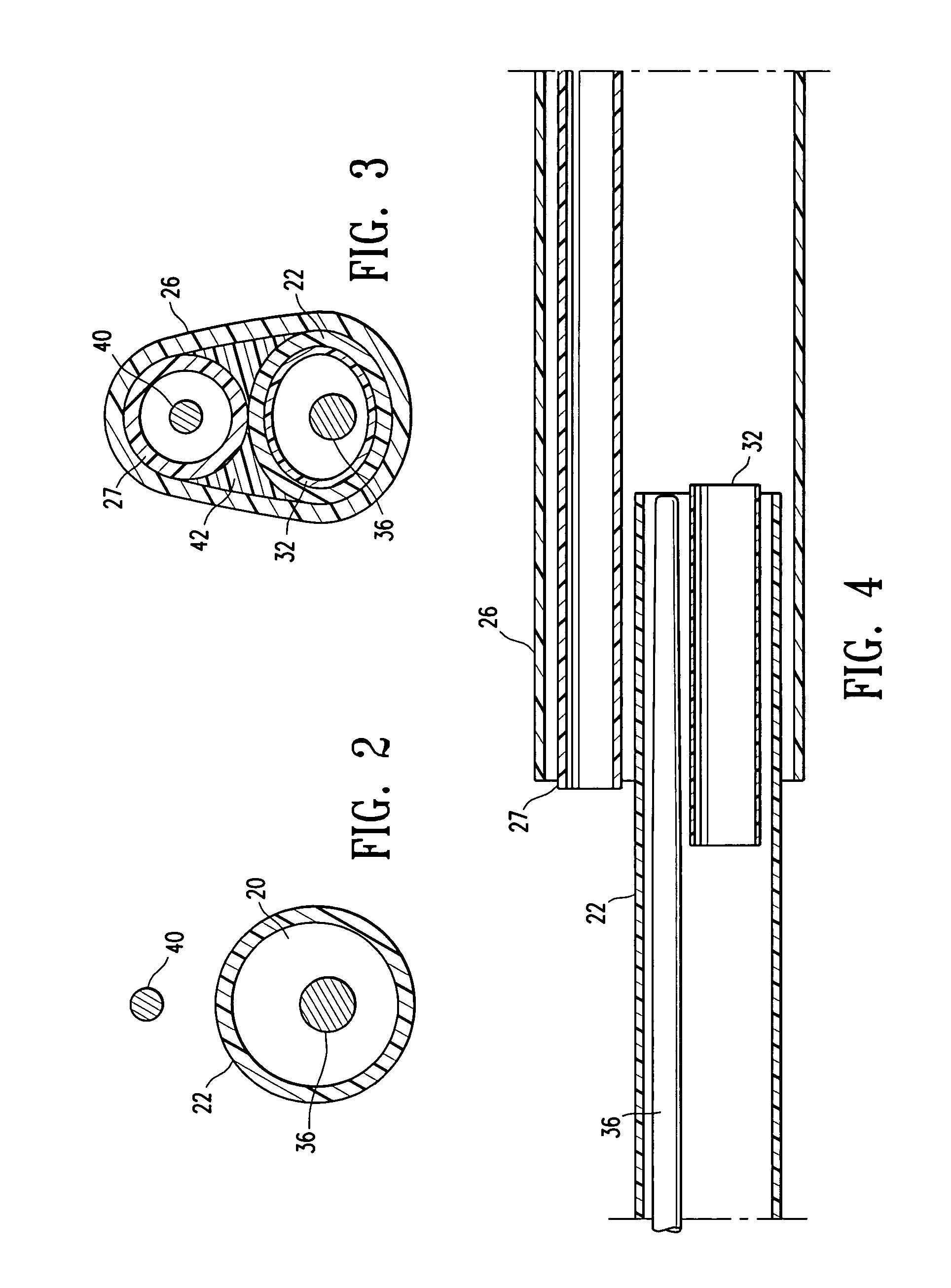
[0009] The polymeric reinforcing member is preferably a tube having a shape configured to correspond to the shape of the proximal portion of the inner tubular member or the
distal portion of the proximal tubular member, such as a circular, oblong / oval, D-shaped or C-shaped transverse cross section. However, a variety of suitable shapes may be used depending on the shape of the inner tubular member and the proximal tubular member. In a presently preferred embodiment, the polymeric reinforcing member is formed of a first polymeric material having a
glass transition temperature greater than a glass
transition temperature of a second polymeric material forming the
distal portion of the proximal tubular member or the proximal portion of the inner tubular member. The first polymeric material forming the polymeric reinforcing member is preferably a high temperature, high modulus material, having a glass
transition temperature (Tg) of about 300° C. to about 450° C., and a tensile modulus, expressed as a
secant modulus (ASTM D882) of about 350,000 to about 450,000 psi. In one embodiment, the first polymeric material forming the polymeric reinforcing member is selected from the group consisting of thermoset
polyimide and
thermoplastic polyimide. The thermoset or
thermoplastic polyimide has a high
secant modulus of greater than about 350,000 psi, with about 25,000 to about 30,000 psi tensile strength, which allows for a thin-walled reinforcing tube which nonetheless has a sufficient strength to provide the required reinforcement. In a presently preferred embodiment, thermoset polyimide is used, due to the high glass
transition temperature of the thermoset polyimide. The thermoset polyimide has a very high glass transition temperature (Tg) of approximately 400° C. (as measured by
differential scanning calorimetry (DSC)), and thus excellent dimensional stability at the
processing temperature of other polymers such as polyamides and polyurethanes commonly used in catheter components. As a result, the polyimide tube maintains thin-walled, controlled dimensions during formation and
assembly of the catheter, and specifically during high temperature fusion (i.e., thermal) bonding of the tubular members to form the rapid exchange junction.
Thermoplastic polyimide, which has a Tg of about 250° C., may also be used, but is less preferred than the high glass transition temperature thermoset polyimide.
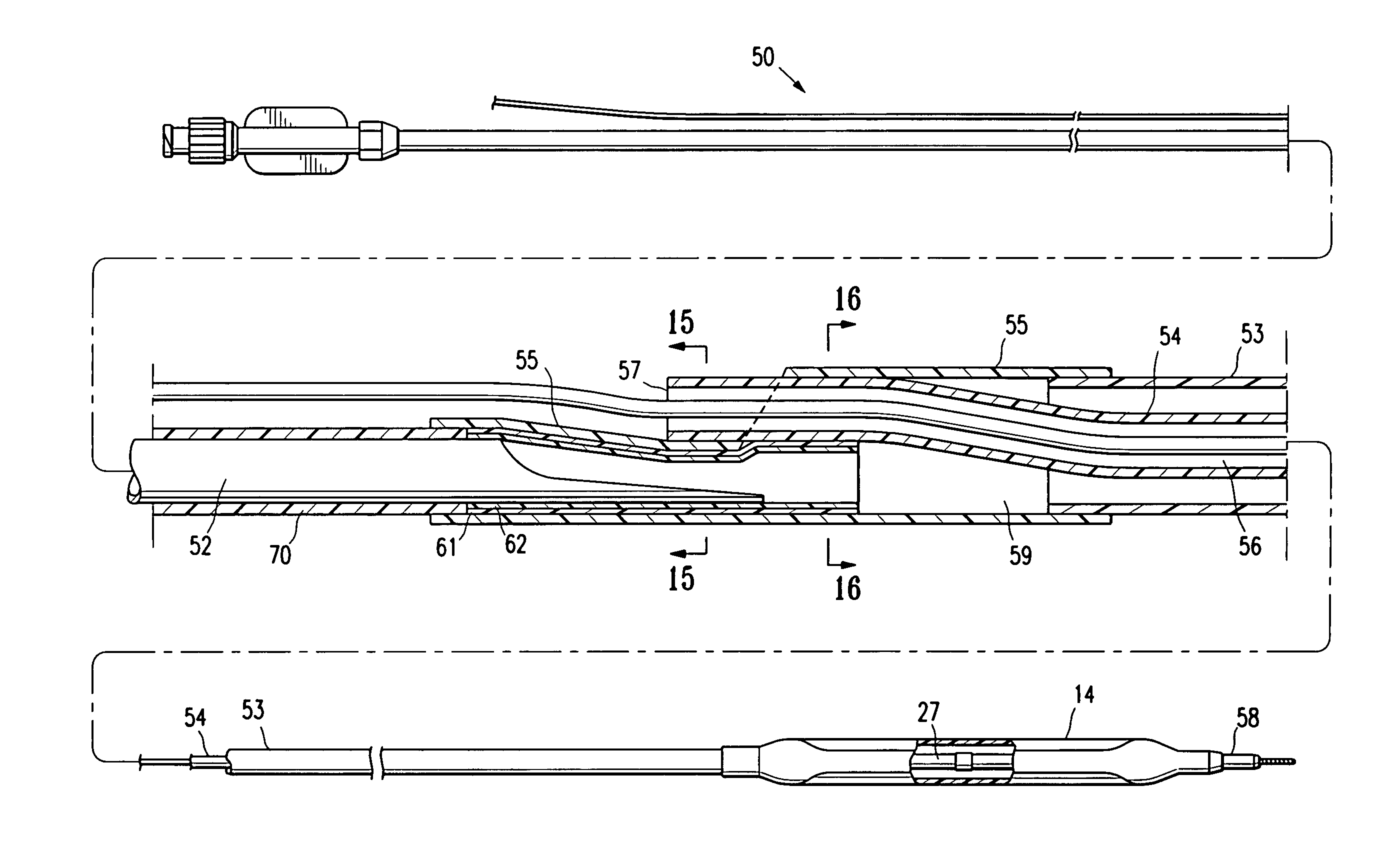
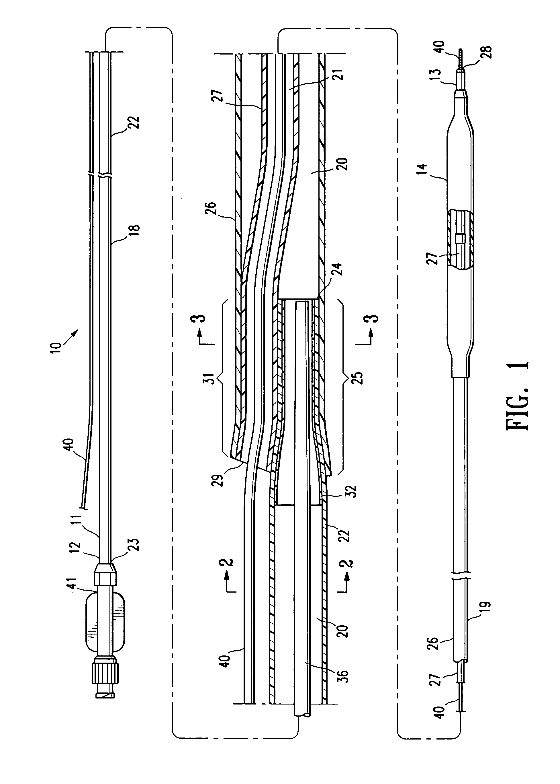
[0011] The polymeric reinforcing member has sufficient wall thickness to prevent or inhibit the formation of a break in the wall of the tubular members defining the inflation lumen and the guidewire lumen at the rapid exchange junction. During
assembly of the catheter, assembly mandrels or rods (hereafter “assembly rods”), are placed in the lumens of the proximal tubular member and the distal inner tubular member, to keep the lumens open during fusion of the tubular members to form the rapid exchange junction. Heat, and pressure from shrink tubing are applied to the tubular members to fusion bond the tubular members together and form the rapid exchange junction at the transition between the proximal or an intermediate shaft section and the distal shaft section at the guidewire proximal port. The polymeric reinforcing member prevents or inhibits loss of integrity of the inner tubular member and proximal tubular member caused by
junction formation as the heated polymeric material of the tubular members are flow together during fusion bonding. Thus, leaks in the guidewire and inflation lumens are prevented or inhibited by the polymeric reinforcing member with a high glass transition temperature.
[0013] In an alternative embodiment, the balloon catheter has a multilayered polymeric sleeve at the rapid exchange intermediate section, with an outer layer formed of a
polymer which has a relatively low
processing temperature (i.e., a relatively low glass transition temperature or
melting temperature), and an inner layer. The outer layer facilitates forming the rapid exchange junction at much lower temperatures than are likely in the absence of the outer layer, thus preventing or avoiding
thinning of the inner layer of the sleeve. The processing temperature is dictated by the glass transition temperature (Tg) for amorphous polymers, and by the melting temperature (Tm) for semi-crystalline polymers. The Tg and Tm values of polymers, as measured by
Differential Scanning Calorimetry (DSC)), are commonly known. In one embodiment, the outer layer of the multilayered polymeric sleeve is selected from the group consisting of an
adhesive polymer such as PRIMACOR (DSC Tm of about 90-100° C.), a relatively low durometer
polyether block amide (PEBAX) having a
hardness of less than about
Shore D 55 (DSC Tm of about 110-160° C.), nylon 6,3 (DSC Tg of about 150° C.), polyaryl
amide (DSC Tg of about 85° C.), nylon 6,12 (DSC Tm of about 145-220° C.), and nylon 12 (DSC Tm of about 170-185° C.), and the inner layer polymer is selected from the group consisting of a relatively high durometer PEBAX (DSC Tm of about 170° C.), and nylons such as nylon 11 (DSC Tm of about 175-195° C.), nylon 6 (DSC Tm of about 190-220° C.), nylon 6,6 (DSC Tm of about 210-270° C.), nylon 6,10 (DSC Tm of about 210-220° C.), nylon 6, 12 (DSC Tm of about 145-220° C.), and nylon 4, 6 (DSC Tm of about 300° C.),
polyphthalamide (DSC Tm of about 145-310° C.), and
polyamide-
imide (DSC Tg of about 280° C.).
[0015] The catheter of the invention maintains the integrity of the inflation lumen and guidewire lumen throughout assembly and use of the catheter, due to the polymeric reinforcing member or multilayered polymeric sleeve. The thin-walled polymeric reinforcing member has excellent dimension stability providing a rapid exchange junction having a low profile and a suitable stiffness transition between proximal and distal portions of the catheter, to thereby improve handling and performance and minimize kinking. These and other advantages of the invention will become more apparent from the following detailed description and exemplary drawings.

