Discretely controlled micromirror with multi-level positions

Active Publication Date: 2005-12-22
STEREO DISPLAY
View PDF83 Cites 27 Cited by
  • Summary
  • Abstract
  • Description
  • Claims
  • Application Information

AI Technical Summary

Benefits of technology

[0020] The VSDCM and the SEDCM can be fabricated with two different methods. The first method uses metals; aluminum, nickel, gold, and copper for structural layer, and photoresist or SiO2 for the sacrificial layers that forms the air gaps. The fabrication of the DCM begins with a wafer on which a completed semiconductor microelectronics circuit is fabricated. A thick oxide is deposited over metal of the semiconductor microelectronics and then planarized using known polishing methods such as chemical mechanical polishing (CMP) techniques and so on. The polishing step provides a completely flat surface for the digital structure. The CMP ensures that thickness variation, flatness and reflectivity of micromirrors are not degraded. Through the use of several photomask layers, the structure of micromirrors is formed with metal layers for the spring, posts, and micromirror layer. And the air gap of

Problems solved by technology

The analog control is more complex than the digital or discrete control, and is not compatible with known semiconductor electronics technologies such as MOS, CMOS,

Method used


Image

  • Discretely controlled micromirror with multi-level positions
  • Discretely controlled micromirror with multi-level positions
  • Discretely controlled micromirror with multi-level positions

Examples


Embodiment Construction

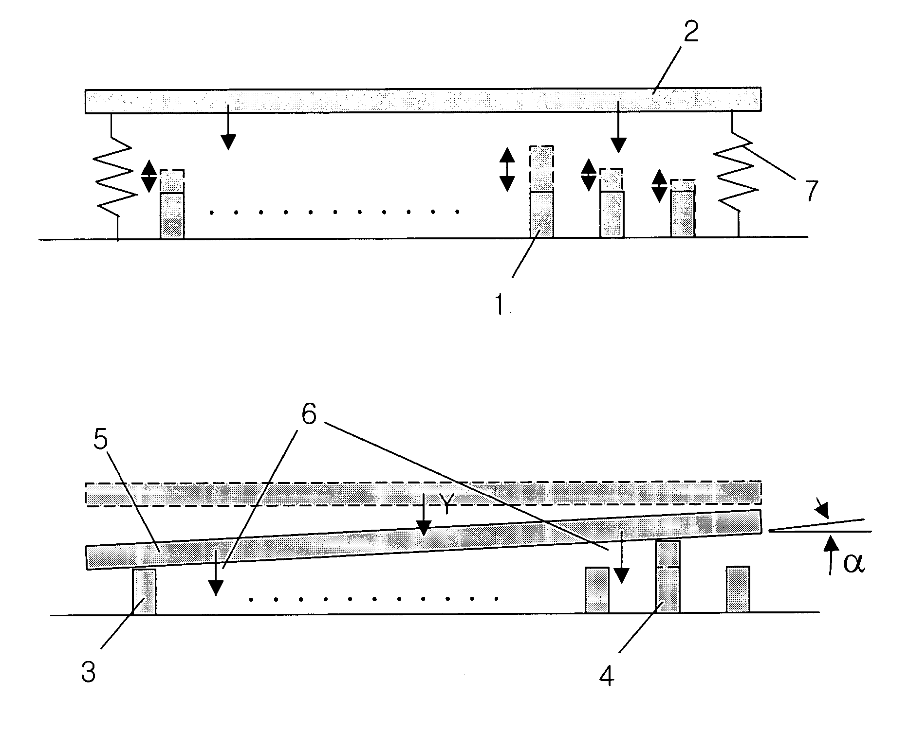
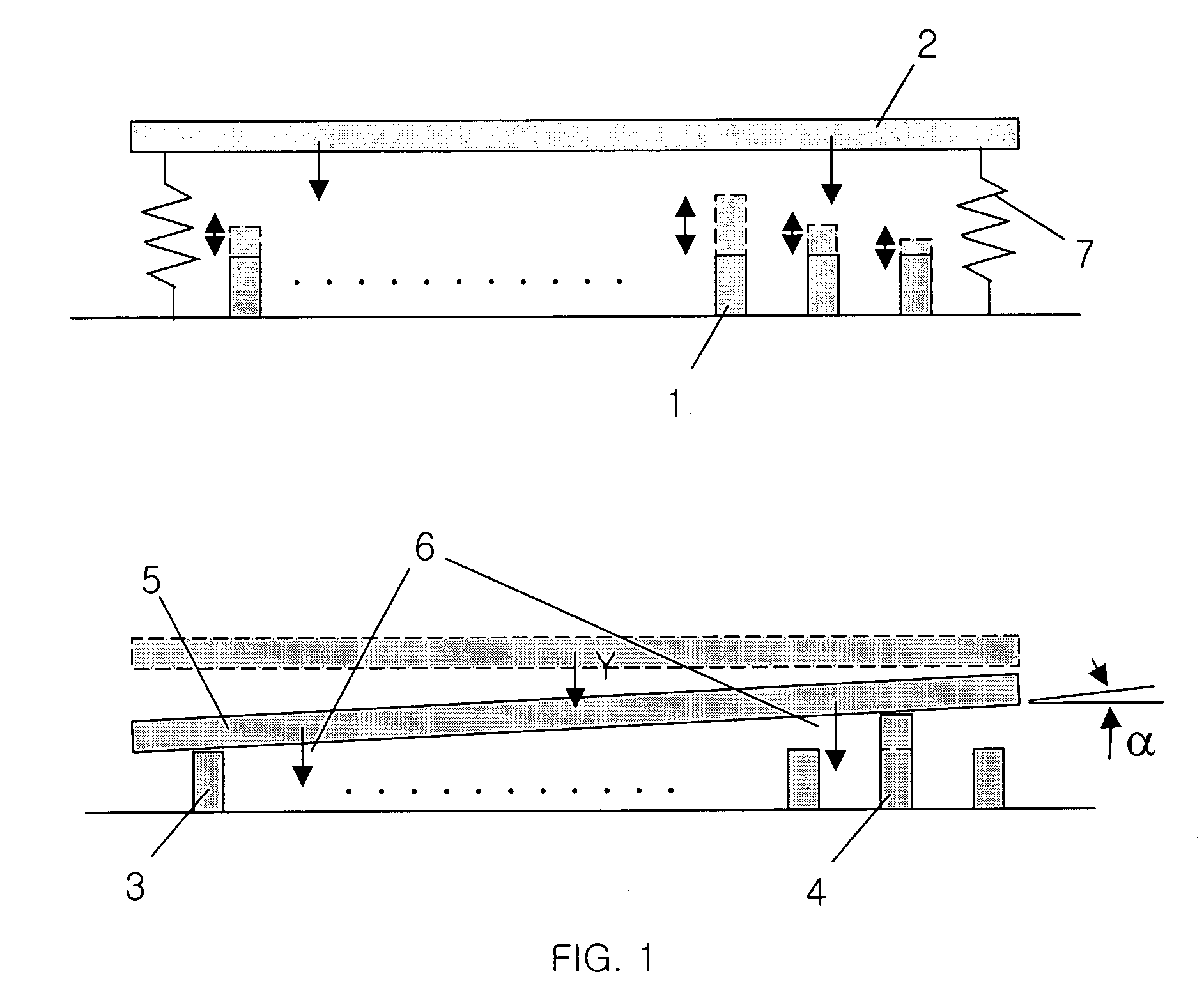
[0061]FIG. 1 shows the concept of DCM with the variable supporters 1. The variable supporter discretely controlled micromirror (VSDCM) use supporters 1 providing various gaps between the micromirror 2 and substrate 8. The supporters 1 are located under the micromirror 2. Translation and rotation of the VSDCM are determined by combination of the gaps, which are determined by variable supporters 3, 4 that the micromirror 5 rests. The gaps determined by the variable supporters are controlled digitally or discretely and the micromirror rests on the controlled supporters 3, 4 by attractive force 6. Therefore, the gaps provided by the supporters determine translation and / or rotation of the micromirror. Gap variation by the supporters is determined by digital or discrete motion of the supporters and the motions are controlled by electrostatic force. Digital voltage or discrete voltage operation is preferable method to control the electrostatic force. The position of micromirror 5 is restor...


PUM


Abstract

This invention provides the two types of Discretely Controlled Micromirror (DCM), which can overcome disadvantages of the conventional electrostatic micromirrors. The first type micromirror is a Variable Supporter Discretely Controlled Micromirror (VSDCM), which has a larger displacement range than the conventional electrostatic micromirror. The displacement accuracy of the VSDCM is better than that of the conventional electrostatic micromirror and the low driving voltage is compatible with IC components. The second type of DCM, the Segmented Electrode Discretely Controlled Micromirror (SEDCM) has same disadvantages with the conventional electrostatic micromirror. But the SEDCM is compatible with known microelectronics technologies.

Description

BACKGROUND OF THE INVENTION [0001] The present invention relates to a micromirror device with discrete multi-level positions. [0002] Micromirror devices have been developed because it can substitute for conventional optoelectronic devices. A phase-only piston-style micromirror was used for phase adaptive optics applications and a rotational micromirror was used to deflect a light. Most of these micromirrors have been controlled to have continuous displacements, which are determined at the equilibrium between electrostatic force and elastic force. The analog control is more complex than the digital or discrete control, and is not compatible with known semiconductor electronics technologies such as MOS, CMOS, etc. In addition, the micromirrors with continuous displacement actuated by electrostatic force undergo the classical snap-down phenomenon when the electric force exceeds the elastic force of mechanical structure. The snap-down phenomenon limits the translational and rotational r...

Claims


Application Information

Patent Timeline
IPC IPC(8): G02B26/08G03H1/16
CPCG02B26/0841B81B3/0051G02B26/105B81B2201/04
Inventor SEO, CHEONG SOOGIM, DONG WOOCHO, GYOUNG ILKIM, TAE HYEON
Owner STEREO DISPLAY
Why Eureka
Try Eureka