Laser drive system reduced EMI noise

a laser drive and emi noise technology, applied in the field of laser drive system reduction emi noise, can solve the problems of shield cost and mechanism restrictions, and achieve the effects of reducing cost, reducing the peak value of emi noise, and diffused spectrum

Inactive Publication Date: 2005-12-22
NAGAOKA YUKI +1
View PDF7 Cites 4 Cited by
  • Summary
  • Abstract
  • Description
  • Claims
  • Application Information

AI Technical Summary

Benefits of technology

[0021] By giving a jitter to the high frequency superposition signal which is superimposed by the current to a laser diode and becomes the origin of an EMI noise, and the switching signal by write-strategy at the time of record, this invention diffuses a spectrum and reduce the peak value of an EMI noise.
[0022] In order that the spectrum of an EMI noise may diffuse, a laser drive, an optical head, and an optical disk drive equipment of this invention in order to give a jitter to a high frequency superposition signal and the switching signal by write-strategy at the time of record, and the peak level of radiation may reduce them, a shield becomes unnecessary, therefore the mechanism restrictions of them are lost, and the advantage that the cost for shielding also becomes unnecessary and the cost reduction of it can be carried out is.

Problems solved by technology

The problem we want to solve is that, a shield required in order to reduce an EMI noise, then mechanism restrictions and cost of a shield required.

Method used


Image

  • Laser drive system reduced EMI noise
  • Laser drive system reduced EMI noise
  • Laser drive system reduced EMI noise

Examples


Embodiment Construction

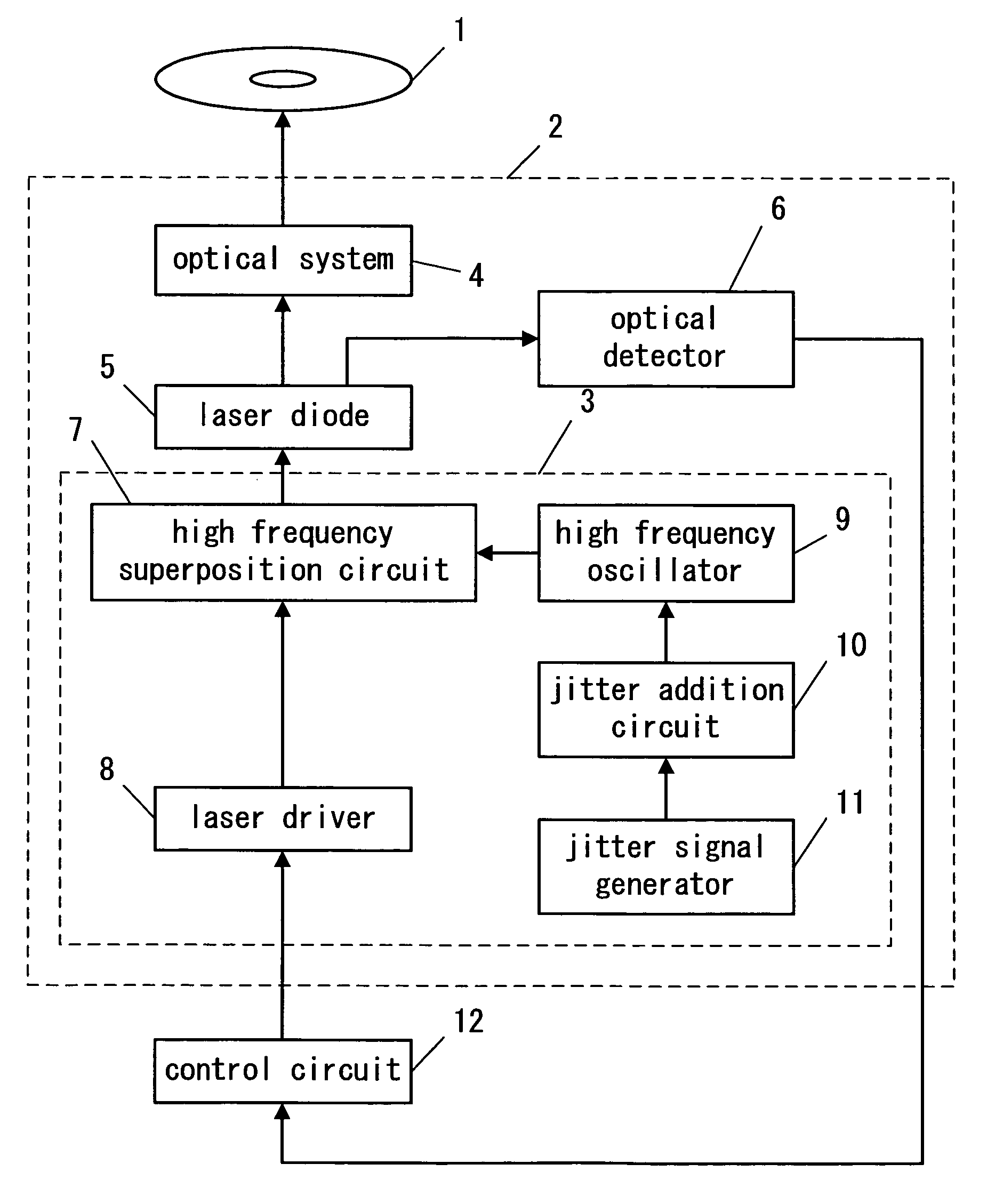
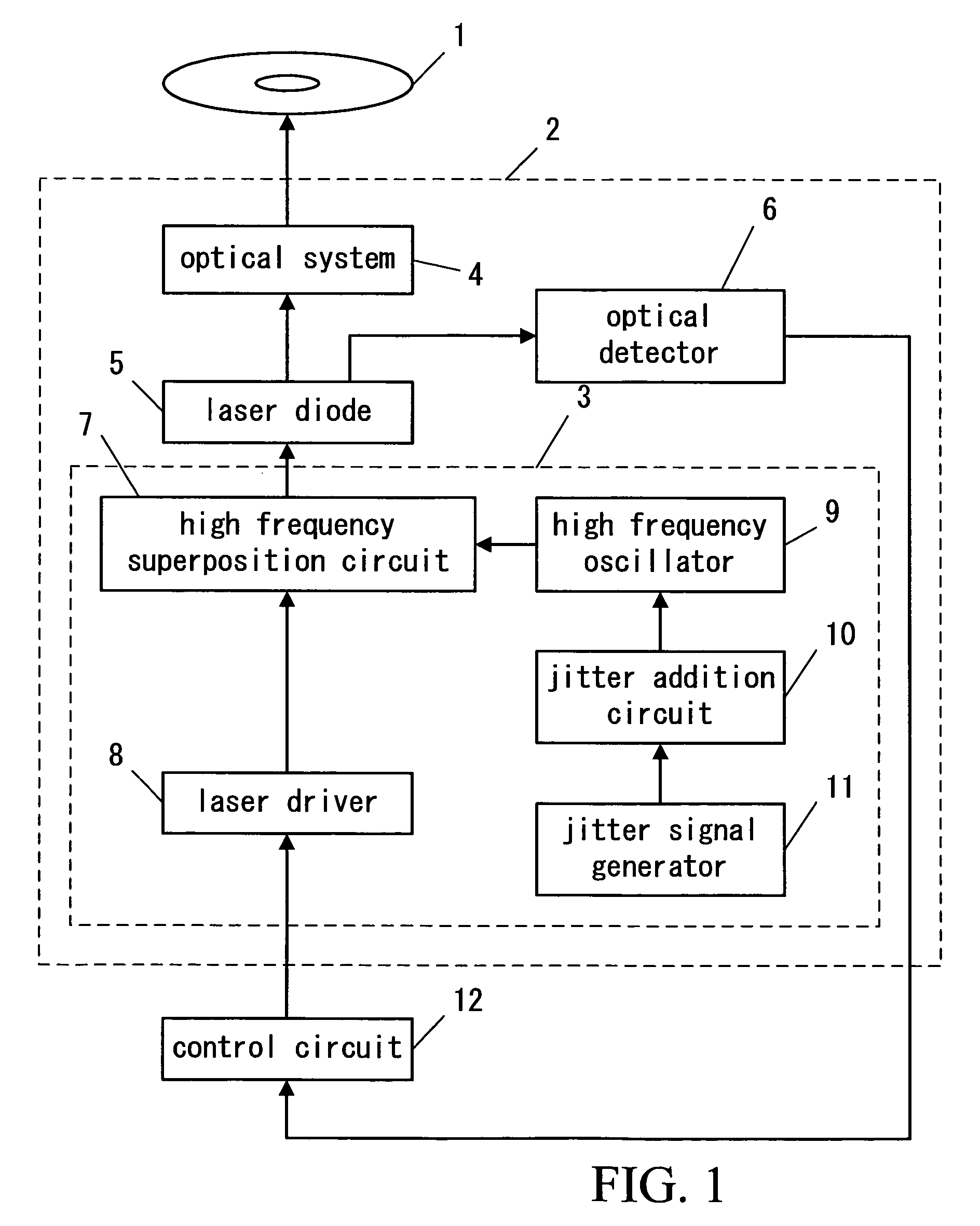
[0041]FIG. 1 is a block diagram of an example 1 of the optical disk drive equipment of this invention.

[0042] Number 1 is an optical disc, 2 is an optical head, 3 is a laser drive unit, 4 is an optical system, 5 is a laser diode, 6 is an optical detector, 7 is a high frequency superposition circuit, 8 is laser driver, 9 is a high frequency oscillator, 10 is jitter addition circuit, 11 is a jitter signal generator, 12 is a control circuit.

[0043] Thus, in the constituted optical disk drive equipment, it is condensed by an optical system 4 and the light emitted from the laser diode 5 is irradiated by the optical disc 1. The part of the light which emitted light from the laser diode 5 is changed into an electric signal with an optical detector 6 as a monitor signal for control of luminescence power, is controlled by a control circuit 12 to become the value as which the monitor signal for control was determined, and drives a laser diode 5 through the laser drive unit 3. It consists of t...


PUM

PropertyMeasurementUnit
delay timeaaaaaaaaaa
frequencyaaaaaaaaaa

Abstract

In optical disc drive, laser diode is used, and also HFM (High Frequency Module) oscillator is used to reduce laser mode hopping noise. Big EMI noise is radiated by the HFM current for optical noise reduction, or by the switching current for write-strategy of recording. Then conventionally, shield was required in order to reduce EMI noise radiated by the current driving a laser diode. By giving a jitter to the HFM signal superimposed to the current of laser diode or switching signal by write-strategy for recording, a spectrum is diffused and the peak value of an EMI noise is reduced.

Description

BACKGROUND OF THE INVENTION [0001] 1. Field of the Invention [0002] This invention is applicable both for laser drive unit, optical head, and optical disk drive equipment, to irradiating laser light when playing back or recording data on optical discs, such as a compact disk and DVD. [0003] 2. Description of the Related Art [0004] Recently laser diode is used for the laser light emitting element of optical disk drive equipment because of small size and low power consumption, but when a laser diode is used as a light source of optical disk drive equipment, the reflected light from an optical disc interferes in the laser oscillation mode of a laser diode, and an optical noise arises. The high-frequency-current superposition method that superimposes AC current of the high frequency from a high-frequency-current drive circuit on DC current to a laser diode which is known as the optical noise reduction method. However, when high frequency current was superimposed, which came with problem...

Claims


Application Information

Patent Timeline
Patent Type & Authority Applications(United States)
IPC IPC(8): G11B7/00G11B7/0045G11B7/125
CPCG11B7/126G11B7/00454
Inventor NAGAOKA, YUKIYASUDA, HIROSHI
Owner NAGAOKA YUKI
Why Eureka
Try Eureka