Continous flow thermal device

a thermal device and continous technology, applied in the direction of biomass after-treatment, filter regeneration, refrigeration machines, etc., can solve the problems of cumbersome physical separation of heating zones from each other, inconvenient real-time monitoring of the course of reaction, etc., to reduce turbulent flow, prevent vaporisation, and reduce the effect of heat loss

Active Publication Date: 2005-12-22
QIAGEN GMBH
View PDF5 Cites 62 Cited by
  • Summary
  • Abstract
  • Description
  • Claims
  • Application Information

AI Technical Summary

Benefits of technology

[0042] As described in our earlier patent (U.S. '183), it is important that back pressure be applied at the end of the fluid stream. As mentioned above, back pressure is suitably between about 300 and about 700 kPa and is achieved by methods known in the art. Specifically, it may be achieved by use of a spring and ball device at the outlet wherein adjusting the tension of the spring sets the pressure. The effect of this is to prevent vaporisation of the fluid stream and reaction mixtures as they pass through the zones of high temperature. As also described in our earlier patent, in order to prevent mixing of reaction mixtures, it is preferred that the flow rate and cross-sectional diameter of the fluid stream are such that turbulent flow is avoided and laminar flow is achieved. Therefore, tubing of small diameter, for example about 3 mm (or ⅛ inch) is particularly preferred since it is both beneficial to rapid heat transfer and minimises turbulent flow. The tube diameter could also be decreased to reduce the reaction volume from 20 μL to 1-2 μL. In this instance the diameter would be about 0.5 mm outside diameter and about 0.2 mm (inside diameter).

Problems solved by technology

Although the device described in U.S. '183 was an advance over previous such devices, a major drawback was that since the heating zones are separate it is not convenient to conduct real time monitoring of the course of a reaction.
In addition, having heating zones which are separated from each other physically tends to be cumbersome.

Method used


Image

  • Continous flow thermal device
  • Continous flow thermal device
  • Continous flow thermal device

Examples


example 1

Operation of Injection System

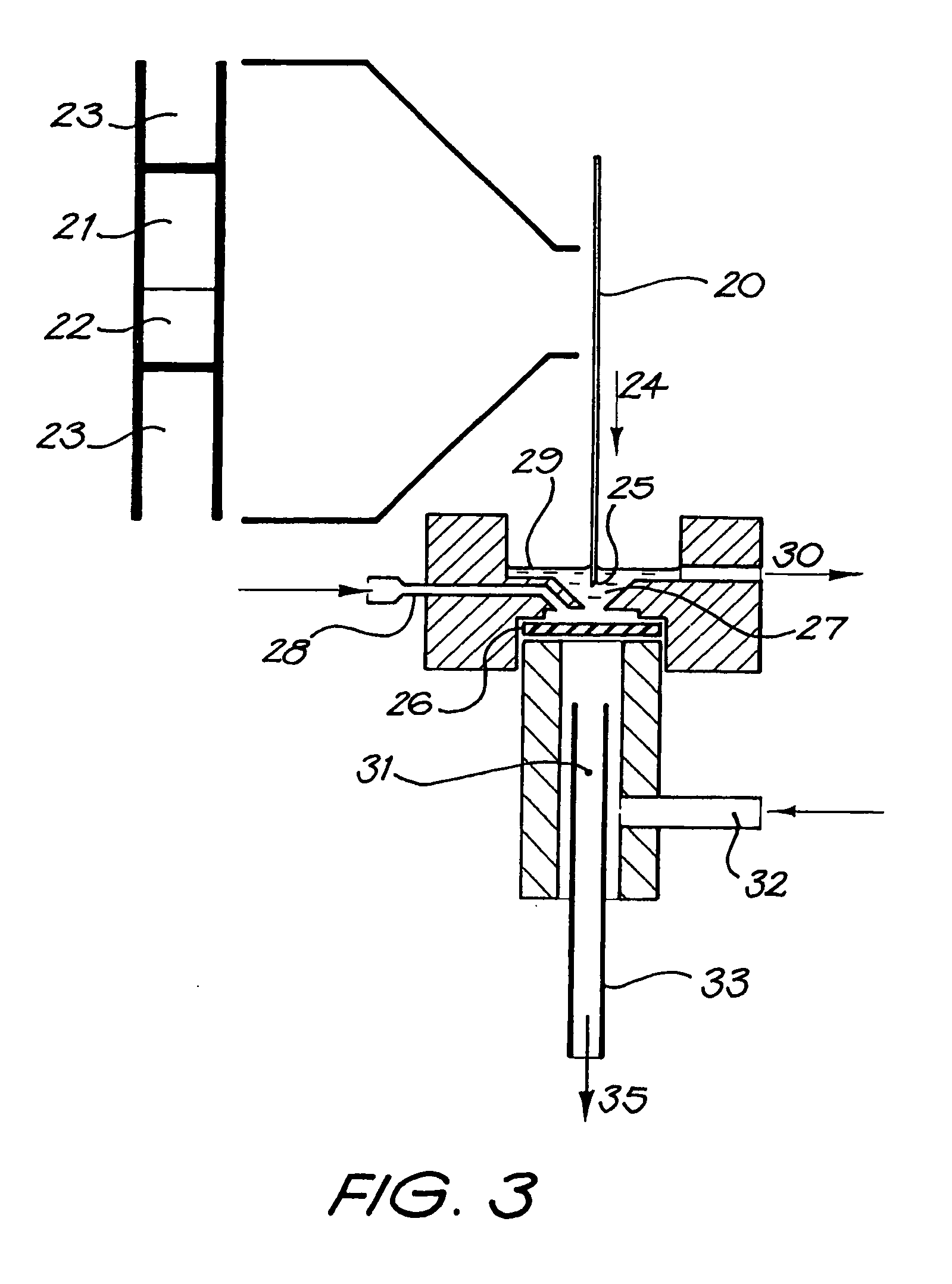
[0071] The following example illustrates the operation of an injection system with the dimensions and parameters set out below. [0072] (A) Injection [0073] (1) The needle is purged with silicon carrier oil. [0074] (2) Sample and reagent are then loaded onto the needle (typically 2-50 μL), then carrier oil is loaded into the needle (typically 10-100 μL). [0075] (3) The needle is placed over the injection port, pushed down through the rubber septum, and into the 1 / 16 PTFE tubing that carries the main oil flow. [0076] (4) The contents off the needle are then injected into the oil stream and the needle is removed from the injector ready to load another sample. [0077] (B) Purging: The purpose of the purge fluid (oil or water flow) is to clean the outside surface of the needle before it passes through the septum. The purge flow is in reverse to that of the needle movement in that the flow comes up from the septum to waste. [0078] (C) Oil Inlet from Pump: A hi...

example 2

DNA Melt Detection Assay

[0079] To detect DNA point mutations it is standard practice to design a synthetic piece of DNA (oligo probe typically a 20 mer) that spans the mutation site. If the probe has been designed to be 100% homologous to the wild type (normal) then these samples will have a higher melting point. For example, when the same probe hybridizes to a mutated DNA sample, there is a base mismatch and the probe is not 100% homologous and so the thermal energy required to denature the probe from the DNA target is less which produces a lower melting point. Thus by comparing melting points of different DNA samples it is possible to determine whether the sample is normal or a mutation.

[0080] Thus, DNA melt detection is carried out using one embodiment of the invention. Reference is made to FIG. 4 which schematically illustrates use of the heat exchanger in this method. That is, the heat exchanger body is heated at one end at approximately 50° C. and at the other end at approxi...


PUM

PropertyMeasurementUnit
temperaturesaaaaaaaaaa

Abstract

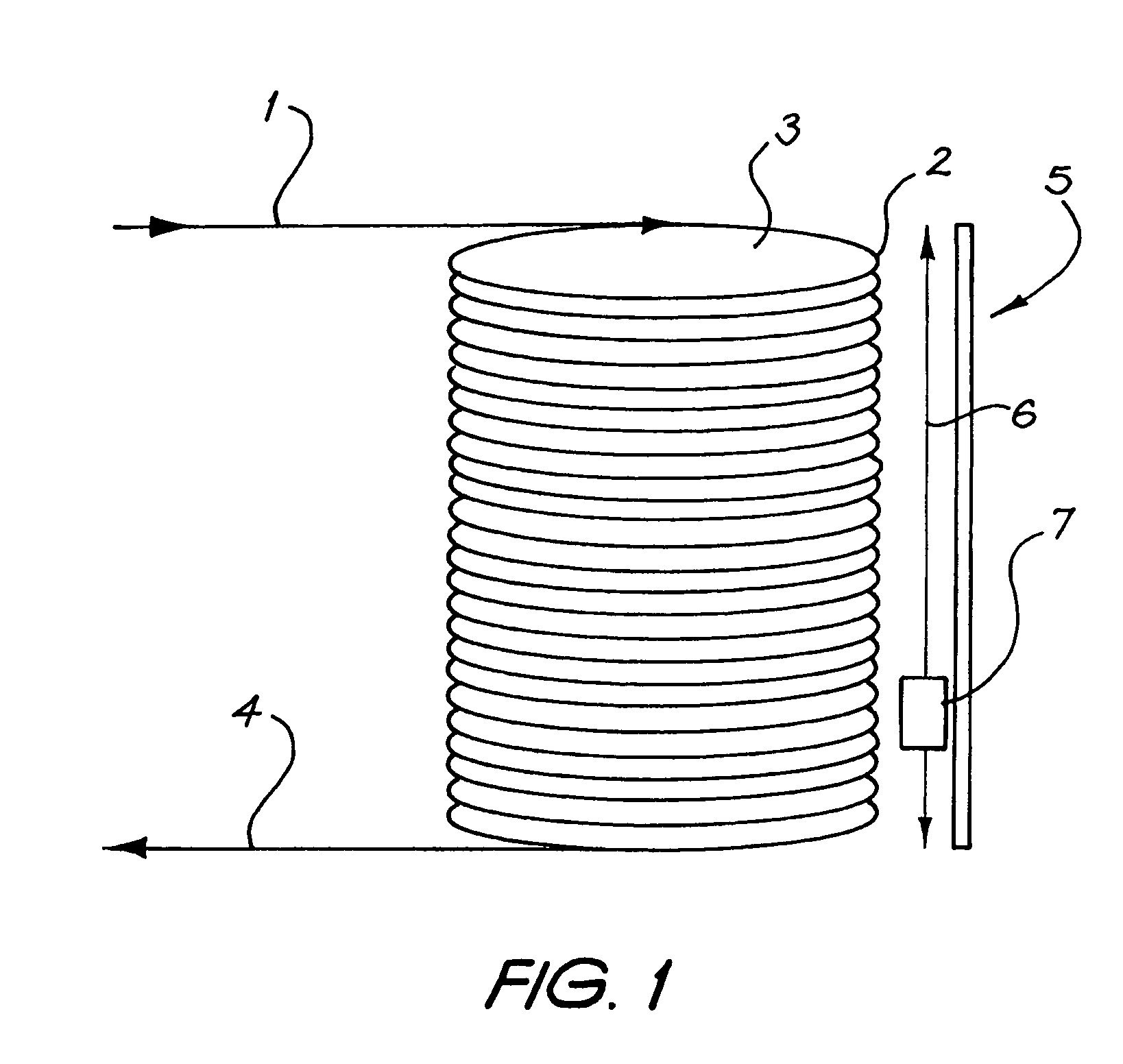
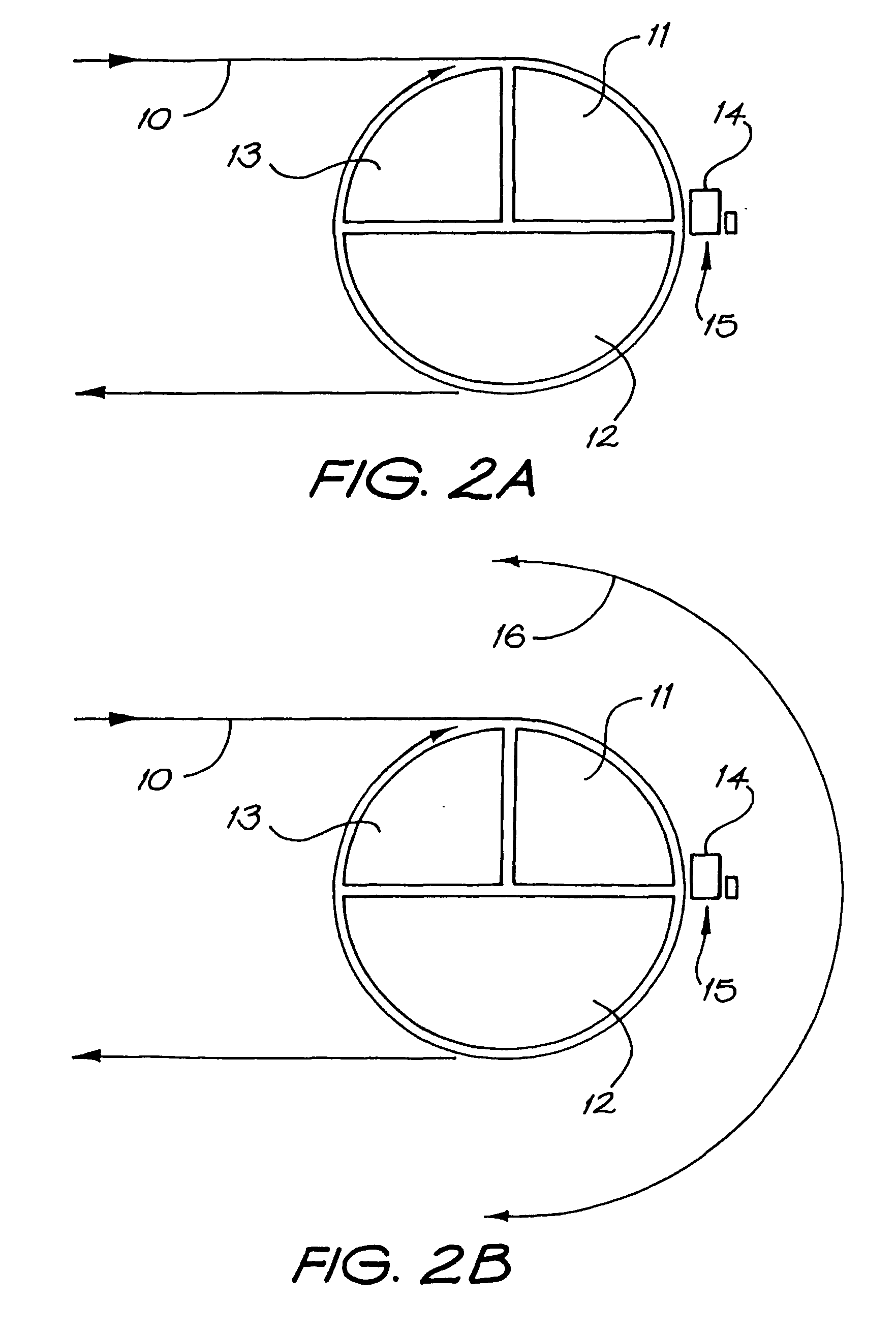
The present invention provides a thermal cycling device including: a heat exchanger body (3) having a longitudinal axis and longitudinally divided to provide at least two segments which are able to be heated to different temperatures so that said body has peripheral surfaces of different temperatures; a conduit (2) extending about said body so as to be in thermal contact with said peripheral surfaces; a first delivery device to deliver a first fluid to said conduit to cause said fluid to pass therealong and therefore change in temperature as the fluid passes said segments; and a second delivery device to deliver a second fluid to said conduit so as to flow with said first liquid and therefore also change in temperature. The fluid then leaves the device by conduit (4). The invention also is directed to an injector means for use in the thermal cycling device of this invention, comprising: a septum (26); a needle (20) which is able to pierce the septum; a reservoir (27) in fluid contact with septum (26) having an inlet (28) and an outlet (30); wherein when in use, the needle is urged through the fluid in said reservoir and then through the septum while continually purging the reservoir with said purge fluid. The present invention also includes a scanning detector (5) fitted to the outside of the heat exchange body (3) which monitors the course of reaction inside the conduit (2).

Description

TECHNICAL FIELD [0001] The present invention relates to a device which is able to control and vary in a cyclical manner, or in a progressive manner, the temperature of a fluid in a tube or is able to maintain fluid in a tube at a constant temperature; and is particularly applicable to monitoring the course of a reaction by real time scanning. It is applicable to a device for amplifying nucleic acids when amplification takes place by use of reactions such as the polymerase chain reaction, the ligase chain reaction and the like, when the device is used to vary temperature; and is also applicable to isothermal reactions when the device maintains the temperature at a constant level. Specifically, the present invention, when it relates to a temperature cycling device, takes reactants through different temperatures in a cyclical fashion where it is necessary that the temperature change be achieved accurately and rapidly. Importantly, the present invention provides a system where the react...

Claims


Application Information

Patent Timeline
Patent Type & Authority Applications(United States)
IPC IPC(8): B01L7/00G01N21/77G01N21/78G01N35/08
CPCB01L7/525B01L2200/026B01L2300/044G01N2021/7786B01L2300/1838G01N21/78G01N35/08B01L2300/1805
Inventor MICHAEL CORBETT, JOHNCORBETT, JOHN MICHAEL JR.
Owner QIAGEN GMBH
Why Eureka
Try Eureka