Rare-earth magnet and manufacturing method thereof and magnet motor

Inactive Publication Date: 2005-12-29
HITACHI LTD
View PDF4 Cites 39 Cited by
  • Summary
  • Abstract
  • Description
  • Claims
  • Application Information

AI Technical Summary

Benefits of technology

[0006] The present invention is performed in view of above, and its object is to provide a rare earth magnet which enab

Problems solved by technology

Therefore, though the coercive force is increased, it is difficult to use the magnet for a magnetic circui

Method used


Image

  • Rare-earth magnet and manufacturing method thereof and magnet motor
  • Rare-earth magnet and manufacturing method thereof and magnet motor
  • Rare-earth magnet and manufacturing method thereof and magnet motor

Examples


example 1

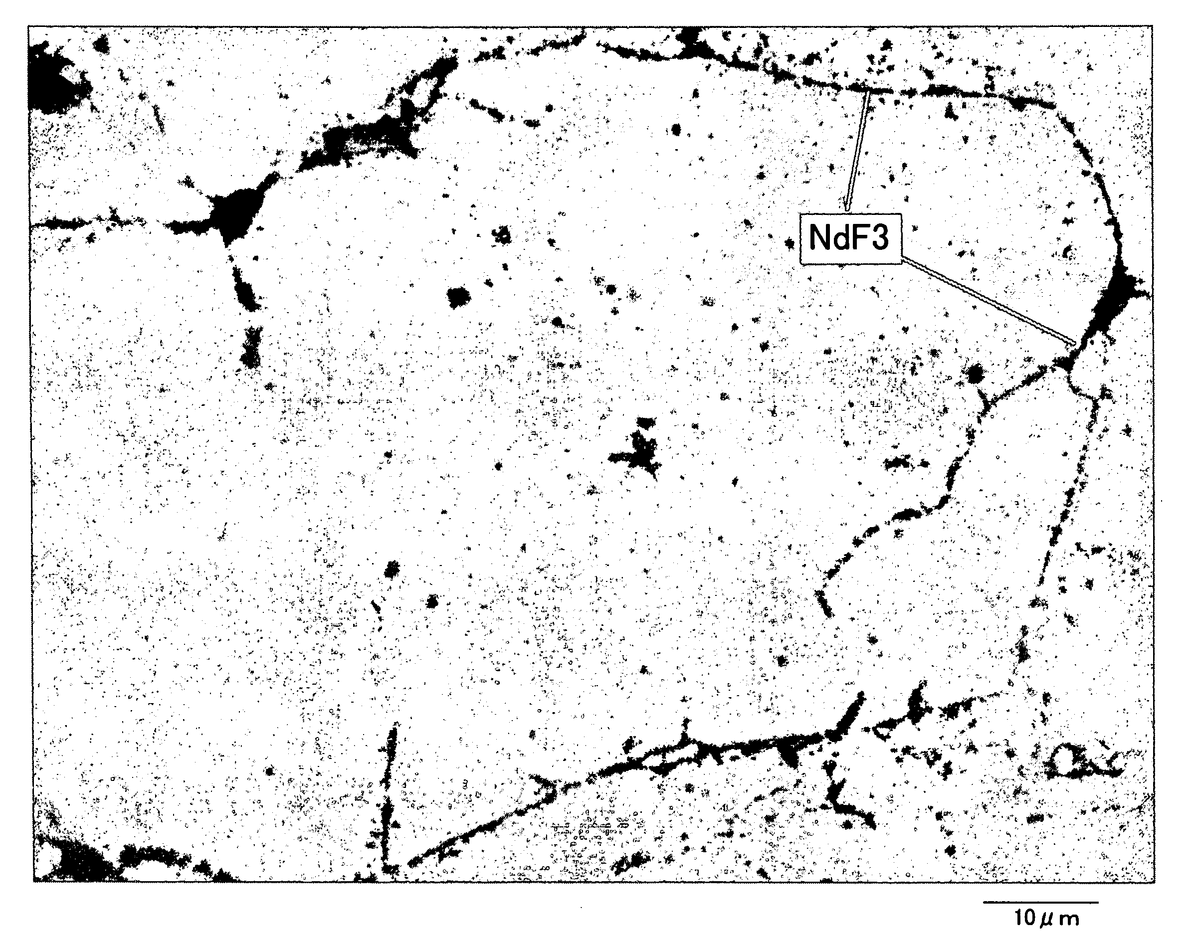
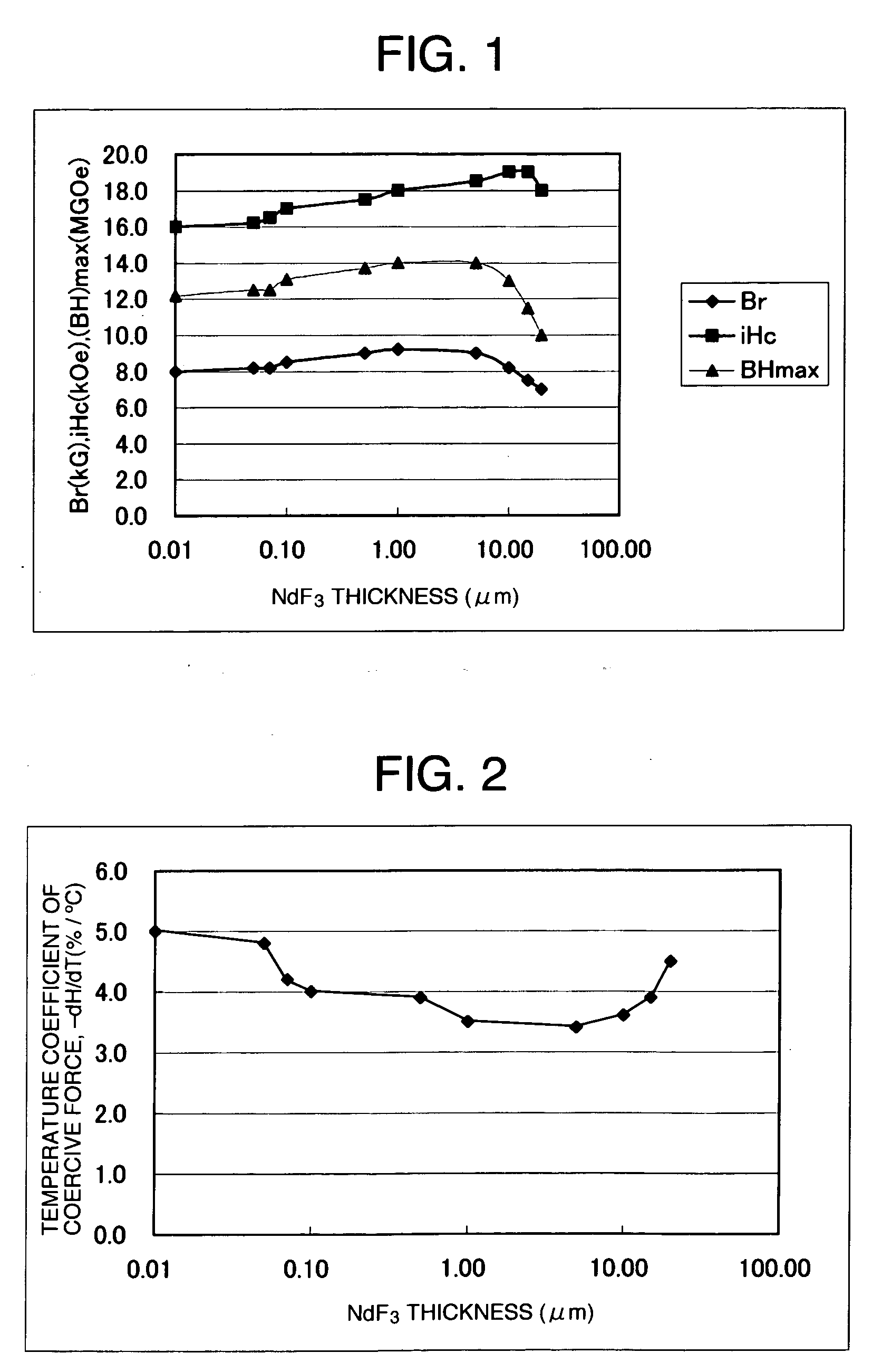
[0023] NdFeB alloy used was a powder having a particle size of about 100 μm subjected to a hydrogenation / dehydrogenation treatment, and the coercive force of this powder was 16 kOe. The fluoride compound to be mixed with the NdFeB powder was NdF3. NdF3 raw material powder was quenched using a quenching apparatus such as in FIG. 7 to form plate-like or ribbon-like powder. As shown in FIG. 7, raw material 102 was molten in an inert gas atmosphere 101 by arc melting using tungsten electrode 103, and by opening a shutter 107 of a nozzle hole 104, the molten NdF3 was atomized on a roll 105 from the nozzle hole 104. Ar gas was used as inert gas, and Cu or Fe based material was used for the roll 105, and the molten NdF3 was atomized on the roll 105 rotating at 500 to 5000 rpm by pressurizing it with Ar gas and utilizing the differential pressure. The resulting NdF3 powder was plate-like, and the NdF3 powder and NdFeB powder were mixed together such that NdF3 content became about 10 wt %. T...

example 2

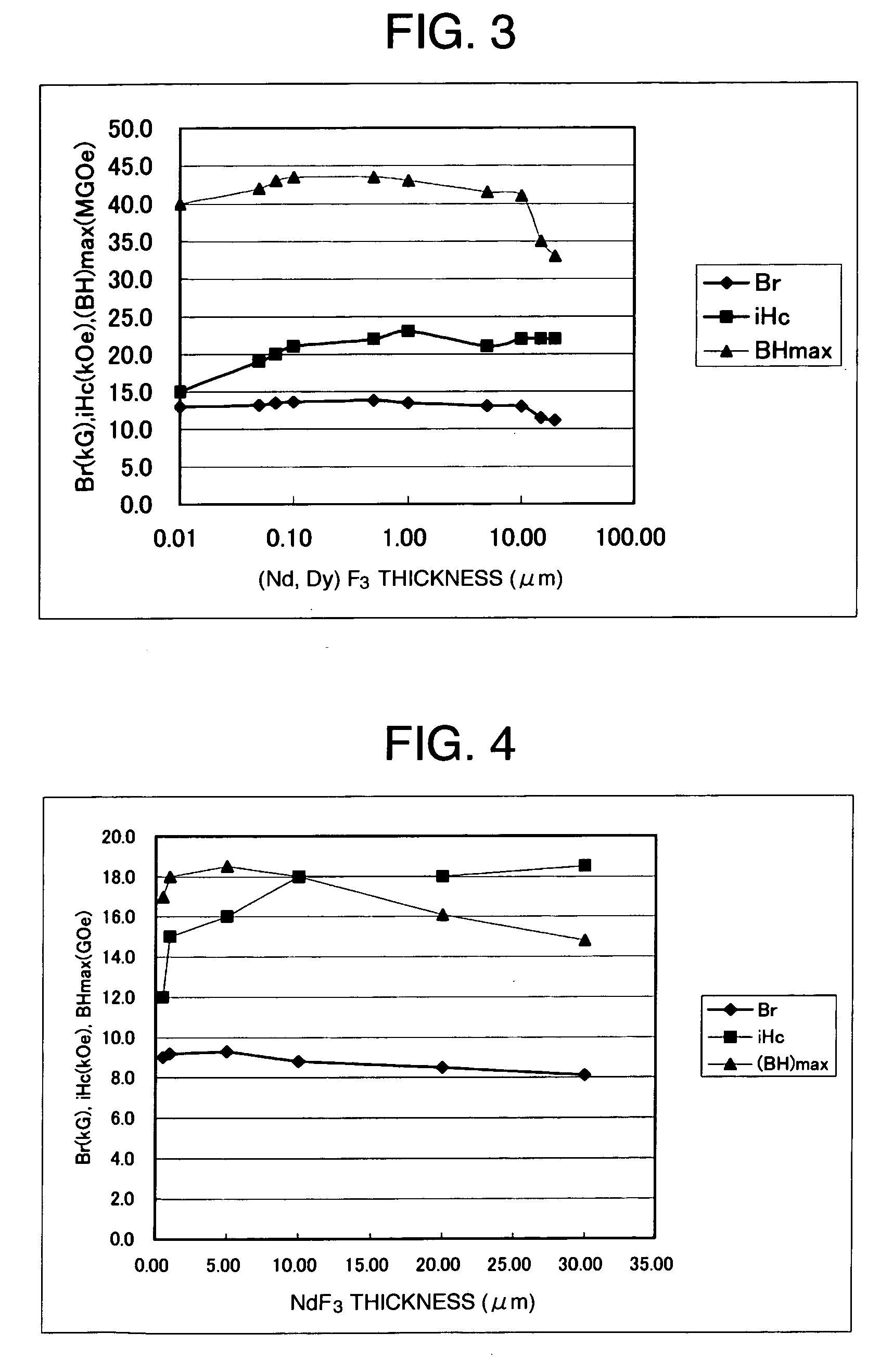
[0026] The NdFeB powder used in the example was intended for use of a bonded magnet or the like. The NdFeB powder used in the example 2 was powder of particle size of 5 μm diameter for use of sintering, in which main phase was Nd2Fe14B, and the grain boundary of the main phase was made of grown Nd rich phase. After being vacuumed to a degree of 1×10⁻⁵ Torr or less, (Nd, Dy)F3 powder was molten in an Ar atmosphere using arc melting, then the molten metal was pressurized and atomized on a surface of a single roll rotating in a vacuum atmosphere. The cooling rate of this processing was 104 to 106° C. / sec. The NdF3-5 wt % DyF3 powder (i.e. (Nd, Dy)F3 powder) formed by quenching, included powder having thickness of 10 μm or less and aspect ratio (the ration of vertical length and horizontal length) of 2 or more. By removing thick powder from such (Nd, Dy)F3 powder, NdF3 powder being as possible as thin was selected to be mixed with Nd—Fe—B alloy powder. The mixing amount of the (Nd, Dy)F...

example 3

[0028] The NdFeB alloy was hydride dehydrated powder having a particle size of 150 μm, and the coercive force of the powder was 12 kOe. The fluoride compound added to the NdFeB powder was NdF3. The raw material powder of NdF3 was pulverized into powder having a mean particle diameter of 0.1 μm. It was mixed with the NdFeB powder such that the content of NdF3 became to 10%. The mixed powder was oriented and compressed using a magnetic field of 10 kOe, and thermally compression molded in a vacuum atmosphere (1×10⁻⁵ Torr) by energization. Under the molding condition of heating temperature at 700° C. and compression pressure of 3 t / cm2, an anisotropic magnet of 7 mm×7 mm×5 mm was made. The densities of the compacts made above were all 7.4 g / cm3 or more. Demagnetization curve of the molded anisotropic magnet was measured at 20° C. by applying a pulse magnetic field of 30 kOe or more in the anisotropic direction thereof.

[0029] The results are shown in FIG. 4. The NdF3 thickness is the av...


PUM


Abstract

The object of the present invention is to provide a rare earth magnet which enables to achieve a good balance between high coercive force and high residual magnetic flux density, and its manufacturing method. The present invention provides a rare earth magnet in which a layered grain boundary phase is formed on a surface or a potion of a grain boundary of Nd2Fe14B which is a main phase of an R—Fe—B (R is a rare-earth element) based magnet, and wherein the grain boundary phase contains a fluoride compound, and wherein a thickness of the fluoride compound is 10 μm or less, or a thickness of the fluoride compound is from 0.1 μm to 10 μm, and wherein the coverage of the fluoride compound over a main phase particle is 50% or more on average. Moreover, after layering fluoride compound powder, which is formed in plate-like shape, in the grain boundary phase, the rare earth magnet is manufactured by quenching the layered compound after melting it at a vacuum atmosphere at a predetermined temperature, or by heating and pressing the main phase and the fluoride compound to make the fluoride compound into a layered fluoride compound along the grain boundary phase.

Description

FIELD OF THE INVENTION [0001] The present invention relates to a rare-earth magnet and its manufacturing method, more particularly, relates to a rare-earth magnet having increased coercive force and high energy product and its manufacturing method, and further relates to a magnetic motor using the rare-earth magnet as a rotor. BACKGROUND OF THE INVENTION [0002] Conventional rare earth magnets including fluoride compounds are described, for example, in JP-A-2003-282312. In the technology described in JP-A-2003-282312, the grain boundary phase has a granular fluoride compound, and the size of the grain of the grain boundary phase is several μm. In such a rare earth magnet, if the coercive force is enhanced, the energy product decreases significantly. [0003] Patent literature 1: JP-A-2003-282312 [0004] In the patent literature 1, the magnetic properties of a sintered magnet produced by adding NdFeB powder for sintered magnet and DyF3 that is a fluoride compound is described in table 3....

Claims


Application Information

Patent Timeline
IPC IPC(8): H01F1/057
CPCH01F1/0572Y10T428/2991H01F41/0293
Inventor KOMURO, MATAHIROSATSU, YUICHI
Owner HITACHI LTD
Why Eureka
Try Eureka