Magnetoresistive sensor with refill film, fabrication process, and magnetic disk storage apparatus mounting magnetoresistive sensor

a technology of magnetoresistive sensor and refill film, which is applied in the field of magnetic head, can solve the problems of leakage of sensing current and insufficient removal of deposited layer, and achieve the effects of minimizing deterioration of characteristics, fast etching rate and low etching ra

Inactive Publication Date: 2006-01-12
HITACHI GLOBAL STORAGE TECH NETHERLANDS BV
View PDF7 Cites 12 Cited by
  • Summary
  • Abstract
  • Description
  • Claims
  • Application Information

AI Technical Summary

Benefits of technology

[0021] Hence, the refill film is fabricated in multi-layer films, and materials for the refill film are selected so that the etching rates of layers other than the layer in contact with the magneto-resistance film may become faster than the etching rate of the layer in contact with the magneto-resistance film. Namely, as to the refill film that is fabricated first of the refill film along track width direction or the refill film along sensor height direction, the layer in contact with the magneto-resistance film is formed of a material that is slow in etching rate but possible to minimize deterioration of characteristics due to thermal treatment, and a layer(s) other than the layer in contact with the magneto-resistance film is formed of a material that is fast in etching rates. In this way, the area in a situation that makes the incidence of ion beam hard in the second etching is eliminated while the deterioration of characteristics due to thermal treatment is minimized, resulting in sufficient removal of the re-deposited substance.
[0022] According to the present invention, it is possible to realize a high-output magnetic reading head with less leak of sensing current because re-deposited substance that deposited on the wall surface of the magneto-resistance film in the etching step of the fabrication process can be readily removed. Moreover, it is possible to realize a magnetic read / write apparatus with high recording density by mounting the magnetic reading head of the present invention.

Problems solved by technology

Accordingly, there is a possibility that the re-deposited layer is not sufficiently removed and that leak of sensing current occurs.

Method used


Image

  • Magnetoresistive sensor with refill film, fabrication process, and magnetic disk storage apparatus mounting magnetoresistive sensor
  • Magnetoresistive sensor with refill film, fabrication process, and magnetic disk storage apparatus mounting magnetoresistive sensor
  • Magnetoresistive sensor with refill film, fabrication process, and magnetic disk storage apparatus mounting magnetoresistive sensor

Examples


embodiment 1

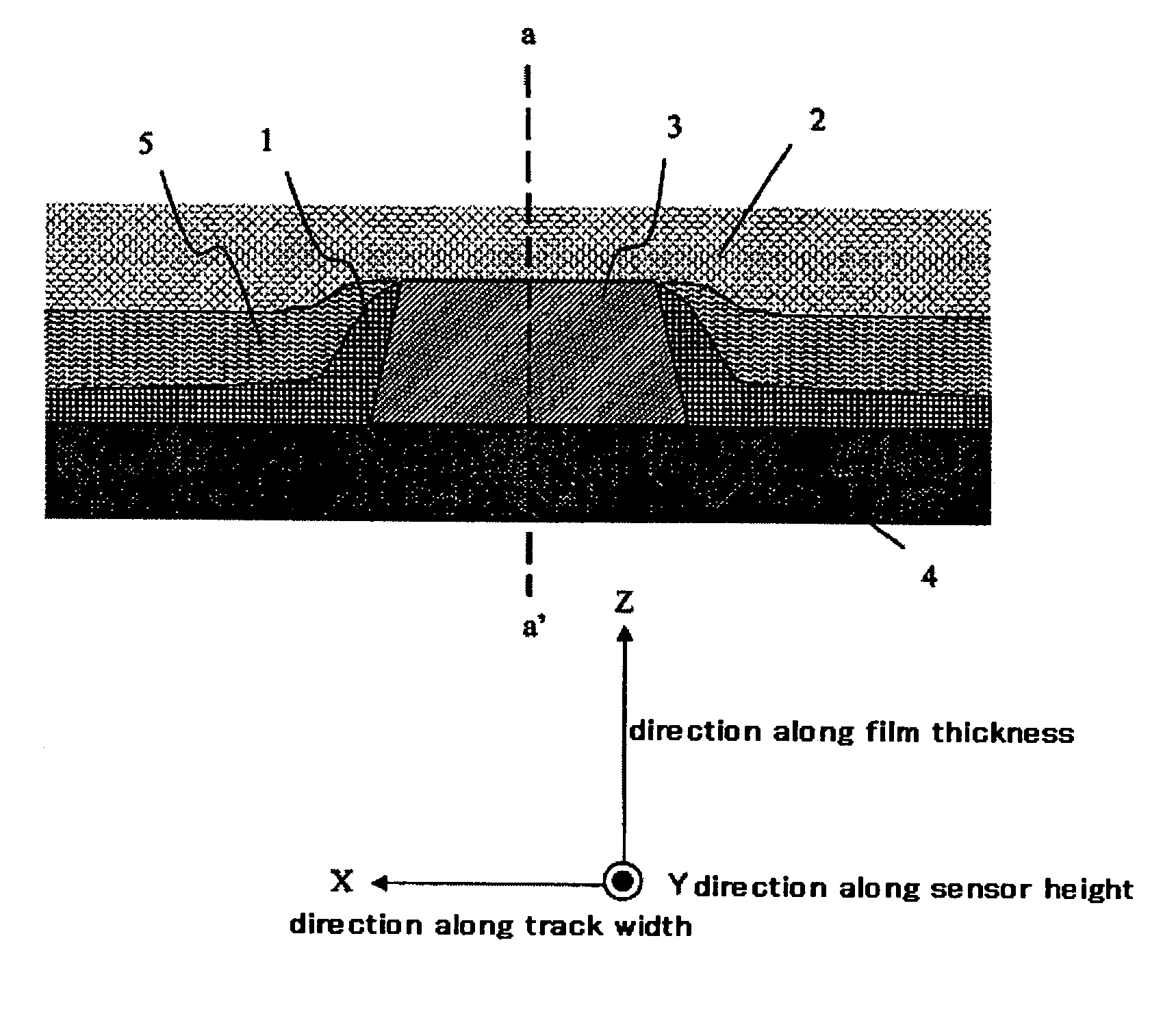
[0050]FIG. 11 is a cross section in the sensor height direction showing a sensor portion of one example of the magnetic reading head according to the present invention. FIG. 12 is an explanatory drawing of its fabrication process and shows cross sections in the sensor height direction in each step.

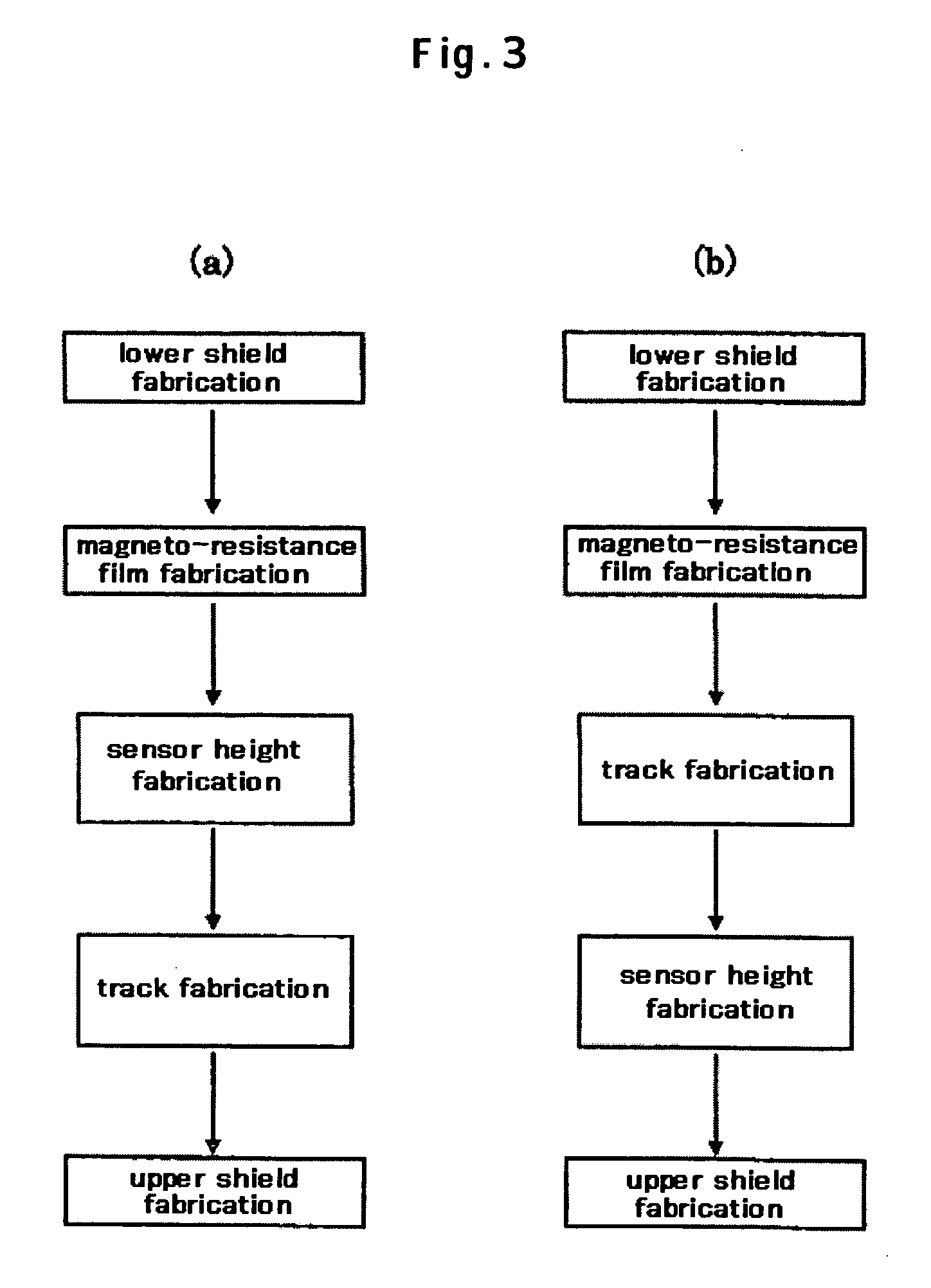
[0051] The fabrication process of the magnetic reading head having the structure shown in FIG. 11 is explained using FIG. 12. It should be noted that the magnetic reading head in the present embodiment is fabricated according to the method in which the step of the sensor height fabrication is carried out before the step of the track width fabrication as shown in FIG. 3(a). First, the substrate surface composed of alumina titanium carbide (AlTiC) or the like is coated with an insulator such as Al2O3 and then subjected to precision polishing by chemical mechanical polish (CMP) or the like to fabricate the lower shield layer 4. This is fabricated by patterning a film composed of nickel-iron ...

embodiment 2

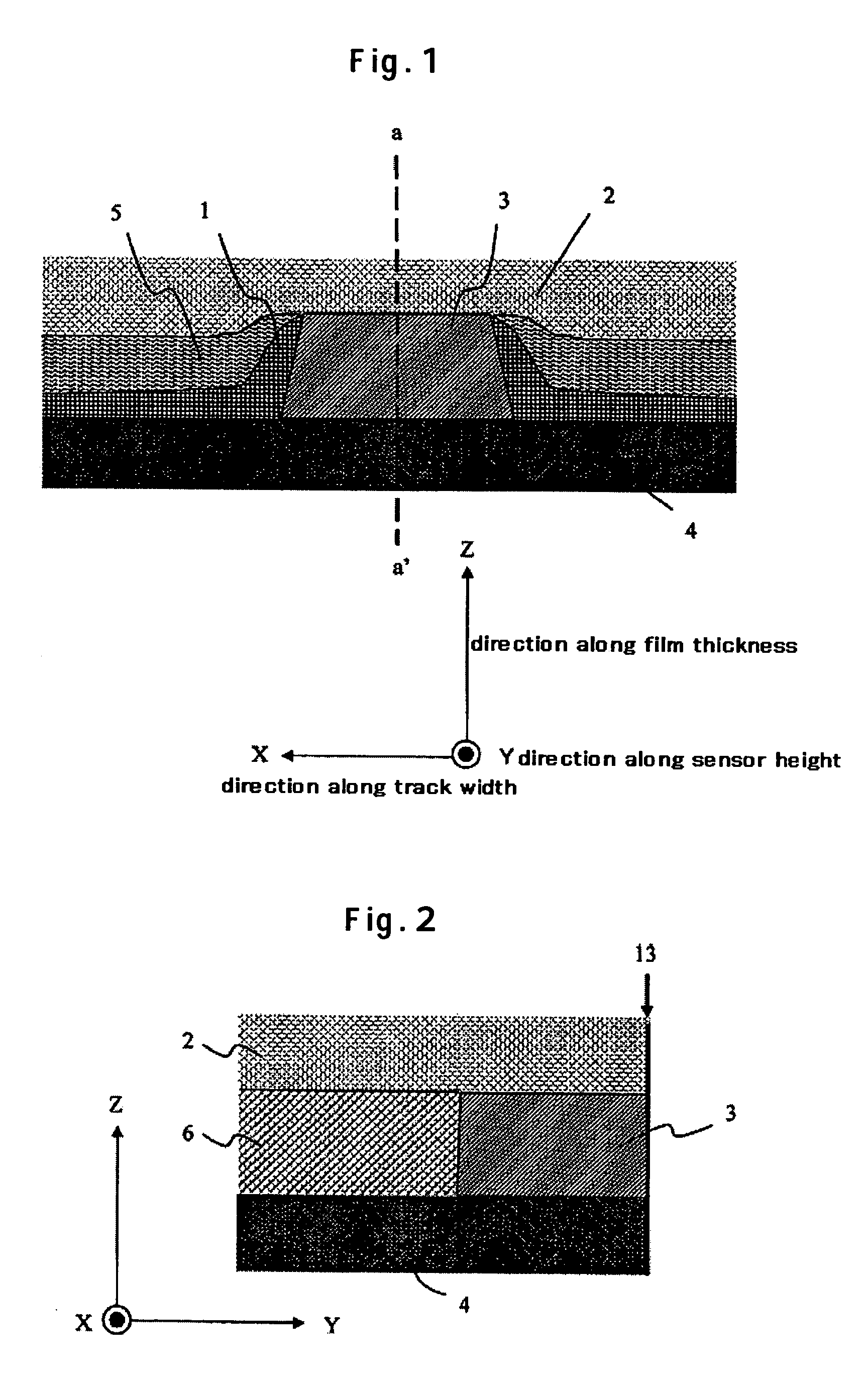
[0072]FIG. 17 is a cross section in the track width direction showing a sensor portion of another example of the magnetic reading head according to the present invention. FIG. 18 is an explanatory drawing of its fabrication process and shows cross sections in the track width direction in each step.

[0073] The fabrication process of the magnetic reading head having the structure shown in FIG. 17 is explained using FIG. 18. First, the substrate surface composed of alumina titanium carbide or the like is coated with an insulator such as Al2O3 and then subjected to precision polishing by chemical mechanical polish (CMP) or the like to fabricate the lower shield layer 4. This is fabricated by patterning a film composed of nickel-iron alloy prepared by, for example, sputtering, ion beam sputtering, or plating in a predetermined shape. By allowing Al2O3 to develop on top of this and subjecting to CMP, the substrate surface becomes a surface of the lower shield layer 4 and Al2O3 planarized....


PUM

PropertyMeasurementUnit
ion incidence angleaaaaaaaaaa
incident angleaaaaaaaaaa

Abstract

Embodiments of the invention provide a high-output magnetic reading head by making it easy to remove a re-deposited substance that deposits on the side wall surface in the track width direction or the side wall surface in the sensor height direction of a magneto-resistance film in a fabrication process of the magnetic reading head. In one embodiment, a refill film that is fabricated first of a refill film along track width direction or a refill film along sensor height direction is fabricated such that a layer in contact with the magneto-resistance film is formed of a material that is slow in etching rate but possible to minimize deterioration of characteristics due to thermal treatment and a layer(s) other than the layer in contact with the magneto-resistance film is formed of a material(s) that is fast in etching rate.

Description

CROSS-REFERENCES TO RELATED APPLICATIONS [0001] This application claims priority from Japanese Patent Application No. JP2004-202343, filed Jul. 8, 2004, the entire disclosure of which is incorporated herein by reference. BACKGROUND OF THE INVENTION [0002] The present invention relates to a magnetic head that allows reading magnetically recorded information, its fabrication process, and a magnetic recording apparatus mounting the magnetic head, and particularly relates to the magnetic head that has a high output and the magnetic recording apparatus mounting this. [0003] A magneto-resistive sensor making use of magnetic resistance effect in which electric resistance changes in response to changes in external magnetic field is known to be an excellent magnetic sensor, and is in practical use as a reading element to detect signal magnetic field from a magnetic recording medium in a magnetic head that is a main component of a magnetic recording apparatus. [0004] The recording density of ...

Claims


Application Information

Patent Timeline
Patent Type & Authority Applications(United States)
IPC IPC(8): G11B5/33G11B5/127G11B5/147
CPCB82Y10/00B82Y25/00G11B2005/3996G11B5/3932G11B5/3909
Inventor MEGURO, KENICHISHINTANI, TAKUWATANABE, KATSUROYOSHIDA, NOBUO
Owner HITACHI GLOBAL STORAGE TECH NETHERLANDS BV
Why Eureka
Try Eureka