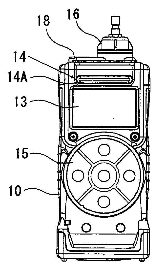
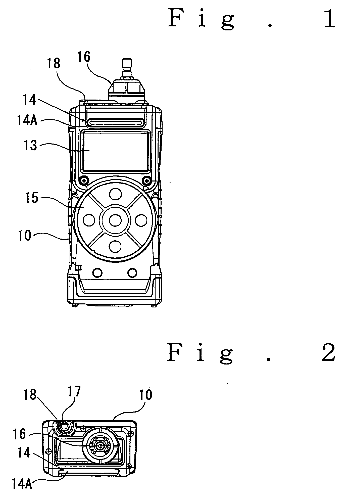
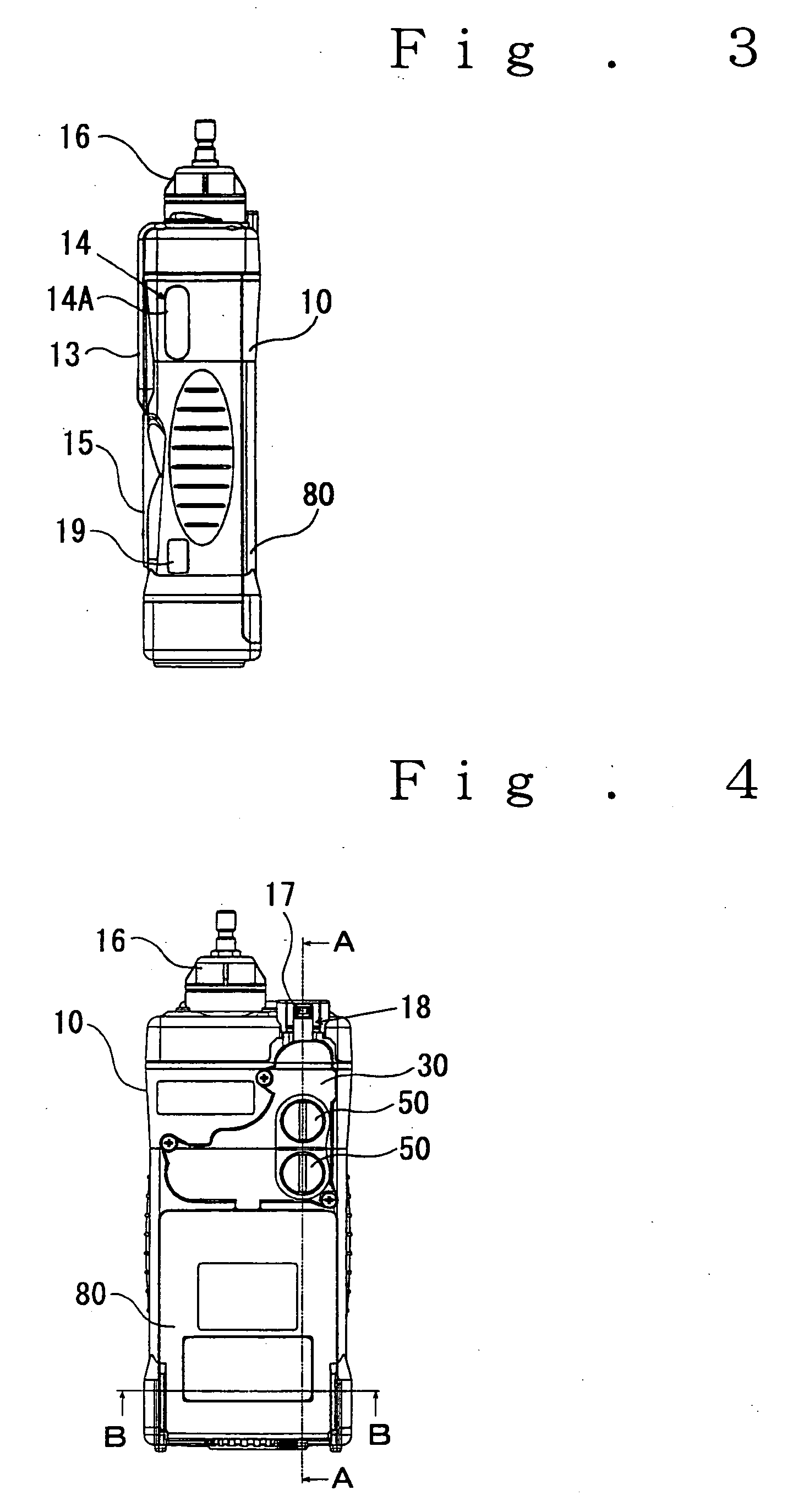
Explosion-proof portable gas detector

a gas detector and portable technology, applied in the direction of instruments, specific gravity measurement, mechanical means, etc., can solve the problems of air in an environmental atmosphere in a dangerous state, fire may be caused, and become dangerous, etc., to achieve high convenience for use, high reliability, and easy manufacturing

Active Publication Date: 2006-01-19
RIKEN KEIKI KK
View PDF3 Cites 28 Cited by
  • Summary
  • Abstract
  • Description
  • Claims
  • Application Information

AI Technical Summary

Benefits of technology

[0016] The present invention has been made on the basis of the foregoing circumstances and fundamentally has as its object the provision of an explosion-proof portable gas detector that is easy...

Problems solved by technology

There are generally frequent occasions when it may be possible in, for example, underground job sites or gateways, or other places where persons enter, or working regions that air in an environmental atmosphere is in a dangerous state, or will become a dangerous state, such as occasions when hazardous gases such as carbon monoxide and hydrogen sulfide gases may possibly...

Method used


Image

  • Explosion-proof portable gas detector
  • Explosion-proof portable gas detector
  • Explosion-proof portable gas detector

Examples


example 1

[0176] Eighty-five parts by weight of (A+B), 15 parts by weight of (C-1), 0.2 parts by weight of (D-1) and 0.8 parts by weight of bis[2-(2-butoxyethoxy)ethyl] adipate were preliminarily dry-blended by a tumbling mixer, and the resultant dry blend was melted and kneaded at a melting temperature of 220 to 270° C. by a co-direction twin-screw extruder having a barrel diameter of 47 mm. A string-like molten resin mixture extruded from a die was cooled in a water tank and chopped by a cutter to prepare pellets of a static charge-controlling resin composition. The result is shown in Table 1.

example 2

[0177] Sixty-five parts by weight of (A+B), 35 parts by weight of (C-1), 0.7 parts by weight of (D-1), 3.8 parts by weight of bis[2-(2-butoxyethoxy)ethyl] adipate and 15 parts by weight of talc were preliminarily dry-blended by a tumbling mixer, and the resultant dry blend was melted and kneaded at a melting temperature of 220 to 270° C. by a co-direction twin-screw extruder having a barrel diameter of 47 mm. A string-like molten resin mixture extruded from a die was cooled in a water tank and chopped by a cutter to prepare pellets of a static charge-controlling resin composition. The result is shown in Table 1.

example 3

[0178] After 40 parts by weight of (A-1) and 40 parts by weight of (B-1) were melted and kneaded at a melting temperature of 240 to 270° C. by a co-direction twin-screw extruder having a barrel diameter of 47 mm to prepare pellets, 20 parts by weight of (C-1), 0.2 parts by weight of (D-1) and 0.8 parts by weight of bis[2-(2-butoxyethoxy)ethyl] adipate were preliminarily dry-blended with the above-prepared pellets by a tumbling mixer, and the resultant dry blend was melted and kneaded at a melting temperature of 220 to 270° C. by a co-direction twin-screw extruder having a barrel diameter of 47 mm. A string-like molten resin mixture extruded from a die was cooled in a water tank and chopped by a cutter to prepare pellets of a static charge-controlling resin composition. The result is shown in Table 1.


PUM


Abstract

The invention provides an explosion-proof portable gas detector that is easy to be fabricated as a small-sized one handy to carry and high in convenience for use, and has explosion-proofness sufficient in a countermeasure against static electricity and high in reliability. The explosion-proof portable gas detector has at least gas sensors, a signal processing circuit, a display mechanism and a power source part within a housing in the form of a slim and flat box holdable by grasping with a hand. The whole or a part of the housing is formed of a static charge-controlling resin material having an insulating resistance value of at most 1 GΩ and a comparative tracking index of at least 90 V.

Description

BACKGROUND OF THE INVENTION [0001] 1. Field of the Invention [0002] The present invention relates to an explosion-proof portable gas detector, and particularly to an explosion-proof portable gas detector equipped with a gas sucking means for introducing a gas to be detected into it and capable of detecting plural kinds of gas components. [0003] 2. Description of the Background Art [0004] There are generally frequent occasions when it may be possible in, for example, underground job sites or gateways, or other places where persons enter, or working regions that air in an environmental atmosphere is in a dangerous state, or will become a dangerous state, such as occasions when hazardous gases such as carbon monoxide and hydrogen sulfide gases may possibly be contained in air in such an environment, or when the oxygen gas concentration in air may possibly be lowered. [0005] When the air in the environmental atmosphere has become a dangerous state to persons due to high concentration of...

Claims


Application Information

Patent Timeline
IPC IPC(8): G01P1/02G01L19/14
CPCG01N33/0009
Inventor KOYANO, JUNICHITAJIMA, SHUJI
Owner RIKEN KEIKI KK
Why Eureka
Try Eureka