Solder and packaging therefrom

a technology of asolder and a packaging, which is applied in the field of asolder, can solve the problems of increasing the temperature of the maximum temperature of the furnace, the inability to meet the requirements of the application, so as to reduce the temperature of the liquidus, increase the tensile strength, and reduce the effect of aging

Inactive Publication Date: 2006-01-19
NEC CORP
View PDF13 Cites 19 Cited by
  • Summary
  • Abstract
  • Description
  • Claims
  • Application Information

AI Technical Summary

Benefits of technology

[0039] As having been explained above, since the solder in accordance with the present invention does contain a material such as lead, which dissolved into ground due to acid rain, and enters a human body through ground water, the solder is not harmful to a human body.
[0040] A liquidus temperature rises beyond a melting point of conventional Sn-37 wt. % Pb eutectic solder, if Zn is added to Sn at 7 to 10 weight %. The solder in accordance with the present invention lowers the thus raised liquidus temperature by adding bismuth at 6 weight % or smaller, ensuring that a liquidus temperature rises by 10 to 20 degrees relative to a melting point of Sn-37 wt. % Pb eutectic solder. Accordingly, it is possible to carry out soldering at a temperature range in which an electronic component has a resistance to heat and which is the same as a temperature range for conventional Sn-37 wt. % Pb eutectic solder. In addition, it is not necessary to newly prepare a reflow-furnace capable of uniformly entirely heating a substrate, and it is possible to use a reflow-furnace having been used for conventional Sn-37 wt. % Pb eutectic solder, without any change.
[0041] Since the solder in accordance with the present invention contains Ag at 0.1 weight % or smaller in Sn—Zn—Bi solder, the solder can have an increased breaking elongation and an increased tens...

Problems solved by technology

Recently, it has been said that lead might be leaked by acid rain out of industrial wastes of products using Sn-37 wt.
The first problem of the conventional solder is that, as mentioned above, Sn-37 wt.
The second problem is that when an electronic component is mounted on a circuit substrate, a maximum temperature in a furnace exceeds a heat-resistance temperature of the electronic component.
Since the maximum temperature (250 degrees centigrade) is higher than a heat-resistance temperature of a lot of electronic components such as CPU, even if an electronic component is mounted on a substrate, the thus mounted electronic component has almost no reliability.
As an alternative, it would be necessary to design an electronic component to have enhanced heat-resistance, however, in which case...

Method used


Image

  • Solder and packaging therefrom
  • Solder and packaging therefrom
  • Solder and packaging therefrom

Examples


example 1

[0090] There were fabricated four solder alloys having the following compositions.

(Solder 1)

[0091] Zn content: 8 weight % [0092] Ag content: 0.08 weight % [0093] Bi content: 0 weight % [0094] Remainder: Sn

(Solder 2) [0095] Zn content: 8 weight % [0096] Ag content: 0.08 weight % [0097] Bi content: 1 weight % [0098] Remainder: Sn

(Solder 3) [0099] Zn content: 8 weight % [0100] Ag content: 0.08 weight % [0101] Bi content: 3 weight % [0102] Remainder: Sn

(Solder 4) [0103] Zn content: 8 weight % [0104] Ag content: 0.08 weight % [0105] Bi content: 6 weight % [0106] Remainder: Sn

[0107] Then, the solders 1 to 4 were powdered, and powders having a diameter in the range of 20 to 40 micrometers were separated out. Then, the powders were mixed with weakly-active flux such that a content of the flux was 12 weight %, to thereby fabricate four creamy solders.

[0108] Then, those creamy solders were printed onto Cu substrate electrodes formed on circuit substrates, through a metal mask. Then...

example 2

[0117]FIG. 6 illustrates a relation between a Bi content (weight %) and a tensile strength (MPa) in the solder in accordance with Example 2.

[0118] There were fabricated four solder alloys having the following compositions.

(Solder 1)

[0119] Zn content: 8 weight % [0120] Ag content: 0.01 weight % [0121] Bi content: 0 weight % [0122] Remainder: Sn

(Solder 2) [0123] Zn content: 8 weight % [0124] Ag content: 0.01 weight % [0125] Bi content: 1 weight % [0126] Remainder: Sn

(Solder 3) [0127] Zn content: 8 weight % [0128] Ag content: 0.01 weight % [0129] Bi content: 3 weight % [0130] Remainder: Sn

(Solder 4) [0131] Zn content: 8 weight % [0132] Ag content: 0.01 weight % [0133] Bi content: 6 weight % [0134] Remainder: Sn

[0135] Then, a test piece for measuring a tensile strength was cut out of those solder alloy bulks, and a tensile strength test was carried out in accordance with a tensile strength test defined in JIS Z2241.

[0136]FIG. 6 was obtained based on the results of the tensil...

example 3

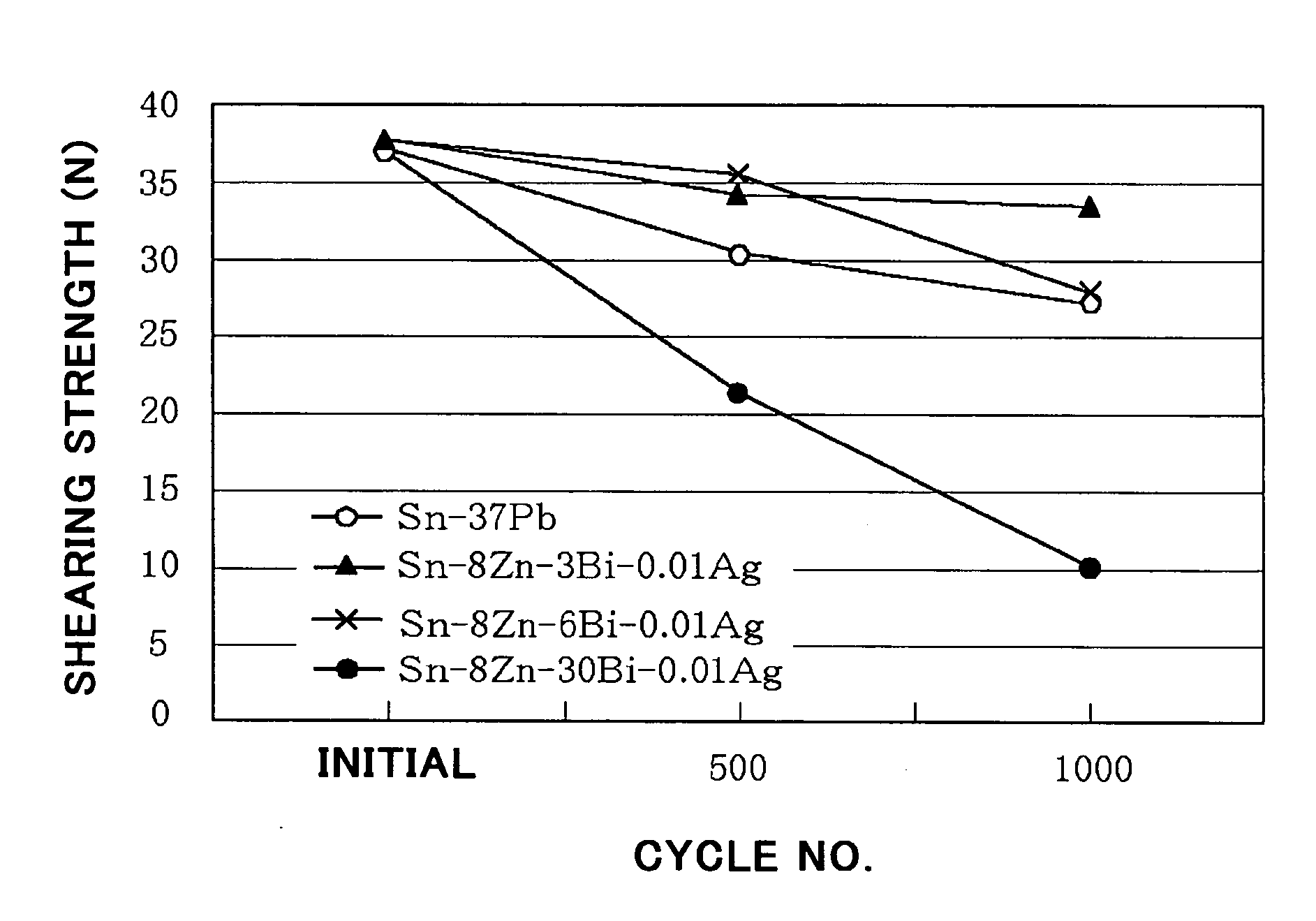
[0139]FIG. 7 illustrates a relation between a thermal cycle and a shearing strength (N) in the solder in accordance with Example 3.

[0140] For comparison, FIG. 7 further illustrates data concerning Sn-37 wt. % Pb eutectic solder.

[0141] There were fabricated three solder alloys having the following compositions.

(Solder 1)

[0142] Zn content: 8 weight % [0143] Ag content: 0.01 weight % [0144] Bi content: 3 weight % [0145] Remainder: Sn

(Solder 2) [0146] Zn content: 8 weight % [0147] Ag content: 0.01 weight % [0148] Bi content: 6 weight % [0149] Remainder: Sn

(Solder 3) [0150] Zn content: 8 weight % [0151] Ag content: 0.01 weight % [0152] Bi content: 30 weight % [0153] Remainder: Sn

[0154] Then, the solders 1 to 3 were powdered, and powders having a diameter in the range of 20 to 40 micrometers were separated out. Then, the powders were mixed with weakly-active flux such that a content of the flux was in the range of 10 to 12 weight %, to thereby fabricate three creamy solders.

[01...


PUM

PropertyMeasurementUnit
Percent by massaaaaaaaaaa

Abstract

The solder contains Sn—Zn alloy(s) having a single composition ratio or a plurality of composition ratios, and Sn—Bi—Ag alloy(s) having a single composition ratio or a plurality of composition ratios. The solder includes zinc at 7 to 10 weight % both inclusive, bismuth at 0.001 to 6 weight % both inclusive, silver at 0.001 to 0.1 weight % both inclusive, and the remainder of tin when the alloys are melted in mixture.

Description

BACKGROUND OF THE INVENTION [0001] 1. Field of the Invention [0002] The invention relates to solder used for mounting an electronic component on a circuit substrate and a circuit substrate unit on which an electronic component is mounted through the solder, and more particularly to lead-free solder, as substitution for conventional Sn-37 wt.% Pb eutectic solder, which is capable of soldering at a temperature in the range of 220 to 240 degrees centigrade, and which has a mechanical strength equal to or greater than that of conventional Sn-37 wt.% Pb eutectic solder, and further to a circuit substrate unit using the lead-free solder. [0003] 2. Description of the Related Art [0004] In mounting an electronic component onto a circuit substrate, there has been conventionally used creamy solder comprised of mixture of Sn-37 wt. % Pb eutectic solder as metal powder, and flux. [0005] The Sn-37 wt. % Pb eutectic solder has an eutectic temperature of 183 degrees centigrade. A reflow-furnace us...

Claims


Application Information

Patent Timeline
IPC IPC(8): B23K35/14B23K35/22B23K35/26C22C13/00H05K3/34
CPCH05K3/3463B23K35/262
Inventor FUNAYA, TAKUOMYOHGA, OSAMUOKADA, YOSHITSUGUKUBOTA, HIROSHISAKURAI, JUNYA
Owner NEC CORP
Why Eureka
Try Eureka