

Techniques for recovering optical spectral features using a chirped optical field
a technology of optical field and target optical spectrum, applied in the field of optical signal processing, can solve the problems of limited performance in the dynamic range of photo-detectors and analog to digital converters, affecting the accuracy of optical spectral features, etc., to achieve the effect of high resolution and fast measurement of spectral features
- Summary
- Abstract
- Description
- Claims
- Application Information
AI Technical Summary
Benefits of technology
Problems solved by technology
Method used
Image

Examples
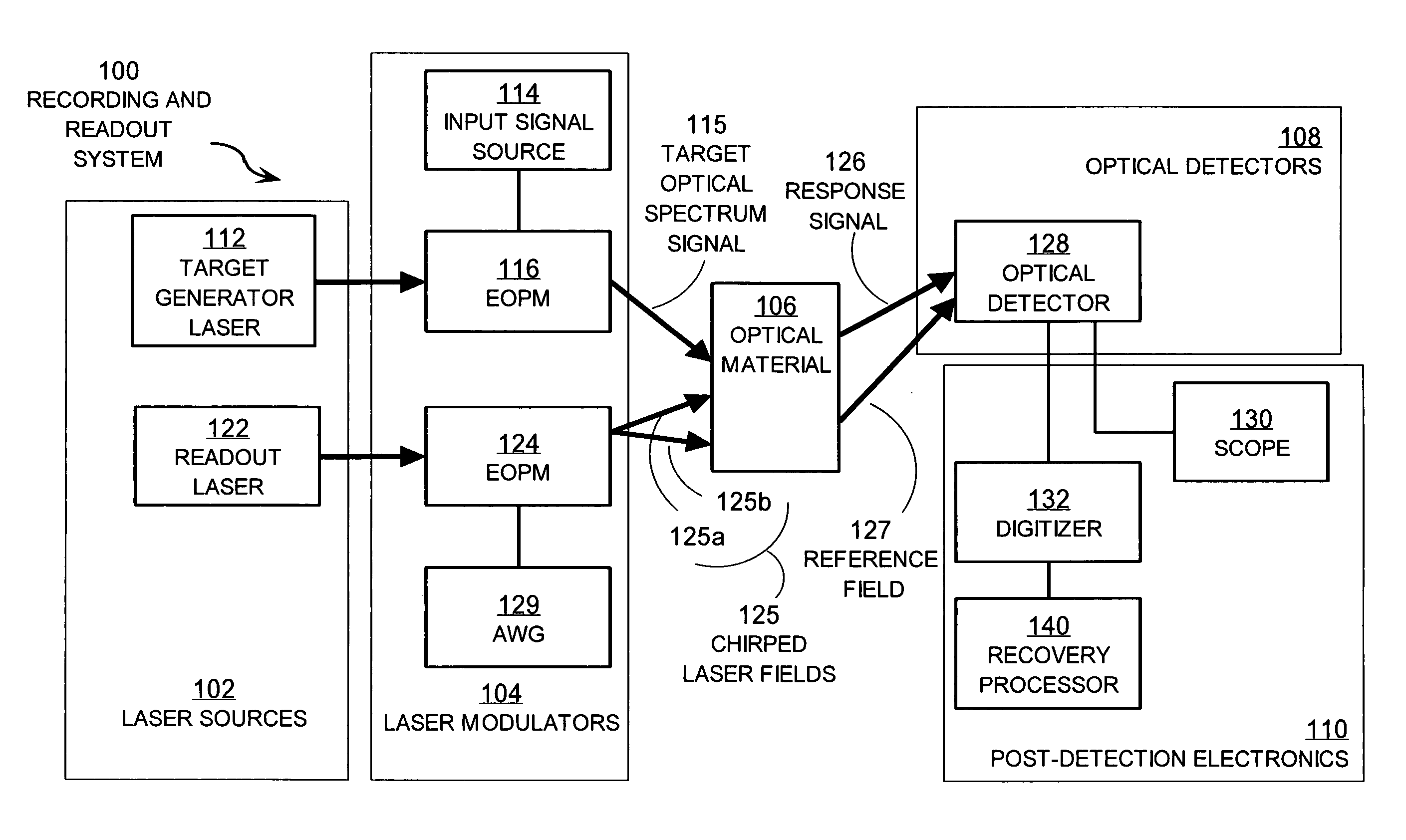
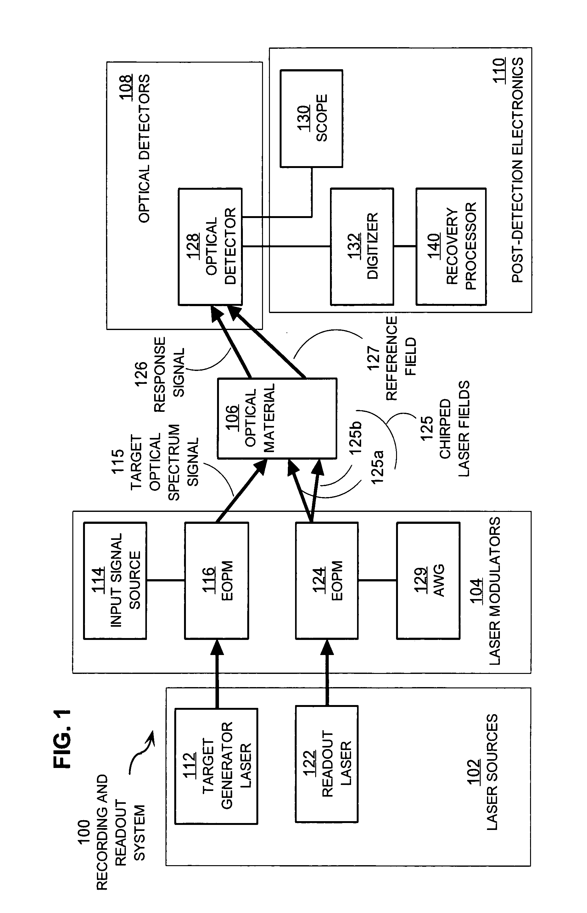
embodiment 100
[0061] In the illustrated embodiment 100, laser sources 102 include an input laser 112 and a readout laser 122. These laser sources provide stabilized optical carrier frequency beams used to carry the target optical spectrum and the chirped laser field used as a probing waveform. In some embodiments, a single laser provides the carrier frequency beam for both the target optical spectrum and probe signals. In some embodiments, additional laser sources are included in laser sources 102.
[0062] The laser modulators 104 modulate the carrier frequency beams to produce signal beams with rich frequency content. In the illustrated embodiment, laser modulators 104 include input signal source 114, electro-optic phase modulators (EOPMs) 116, 124 and arbitrary waveform generator (AWG) 129. In some embodiments, one or more EOPMs 116, 124 are replaced with or added to other optical modulators such as one or more acousto-optic modulators (AOMs), electro-optic amplitude modulators, and electro-absor...
embodiment 241
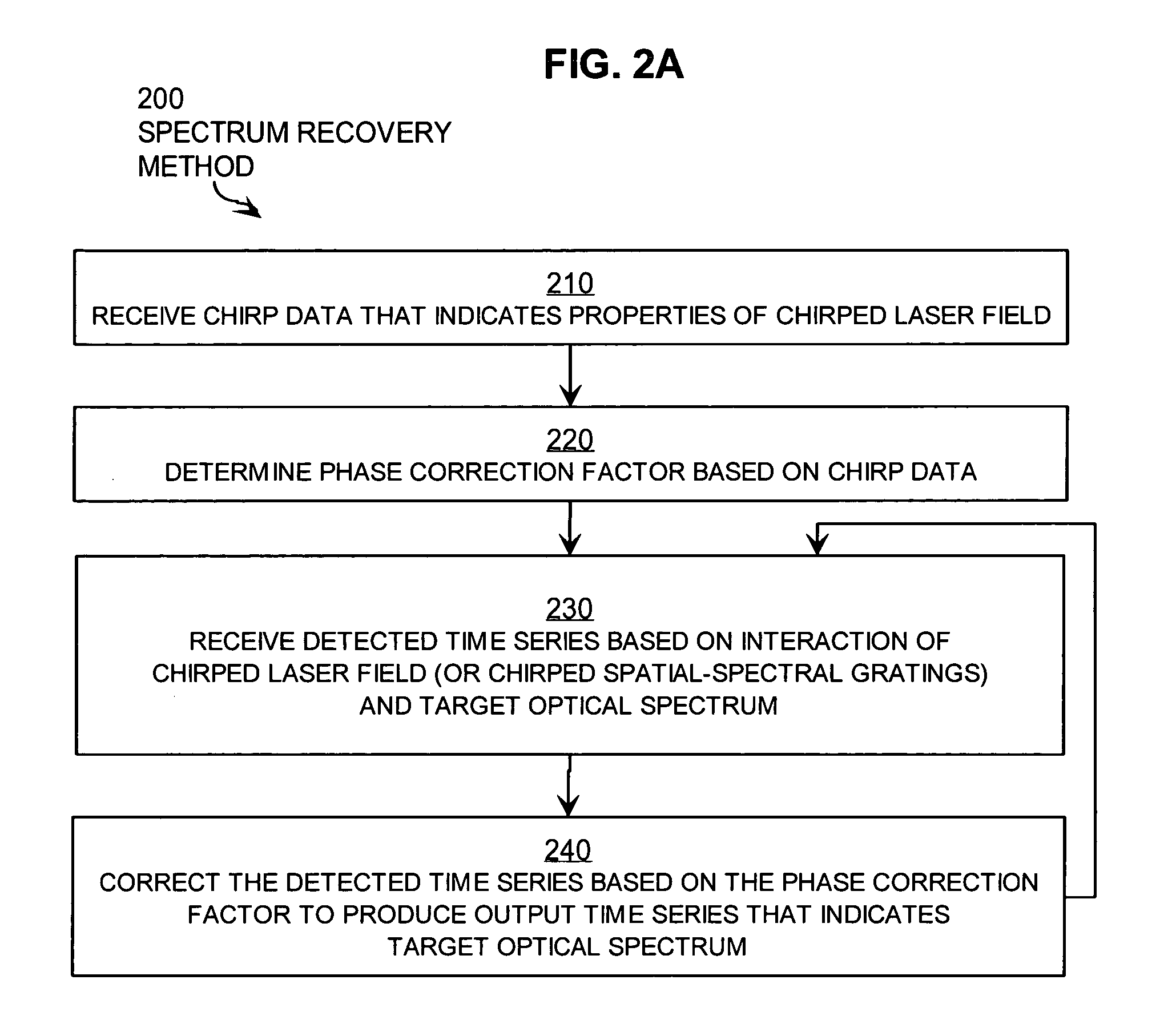
[0092]FIG. 2B is a flow diagram that illustrates in more detail a step of the method illustrated in FIG. 2A, according to an embodiment 241. Step 241 is a particular embodiment of step 240. Step 241 includes steps 252, 254, 256.
[0093] In step 252, the Fourier transform is determined for the detected time series. Any method may be used. There are efficient fast Fourier transform (FFT) software programs and microprocessor chips, which may be used in any combination to perform step 252.
[0094] In step 254, at each frequency, the spectral component in the Fourier transform is multiplied by the correction factor for the corresponding frequency as determined in step 220 to produce a corrected transform. For example, the amplitude of the Fourier transform of the detected series for frequency ν is multiplied by the value of C at frequency ν, as given by Expression 9a, above, to produce the amplitude and phase of the corrected transform at that frequency.
[0095] In step 256, the inverse Four...
embodiment 201
[0096]FIG. 2C is a flow diagram that illustrates in more detail an embodiment 201 of the method illustrated in FIG. 2A. Method 201 is a particular embodiment of step 200, and includes an alternative to step 241. Method 201 implements the correction in the time domain using convolution, the mathematical equivalent of multiplication in the Fourier transform domain. The time domain data processing may be more computationally complex and may require different hardware than used in the Fourier transformed domain. Method 201 includes steps 210, 223, 230, 243. Steps 210 and 230 are as described above for method 200.
[0097] Step 223 is a particular embodiment of step 220, described above. Step 223 includes step 222. In step 222, the inverse Fourier transform of the correction factor is determined. Any method may be used to take the inverse Fourier transform of the correction factor, as described above for steps 252 and 256. There are efficient fast Fourier transform (FFT) software programs a...
PUM
 Abstract
Description
Claims
Application Information