Devices, systems and methods for assisting blood flow

a technology of blood flow and devices, applied in the field of blood pumps, can solve the problems of heart failure, high cost to society, poor quality of life, etc., and achieve the effects of reducing length, reducing weight, and being easy to attach

Inactive Publication Date: 2006-01-19
HEILMAN MARLIN STEPHEN +3
View PDF20 Cites 40 Cited by
  • Summary
  • Abstract
  • Description
  • Claims
  • Application Information

AI Technical Summary

Benefits of technology

[0030] In still a further aspect, the present invention provides an implantable pump for assisting blood flow, including: a flexible conduit; at least one moveable valve to effect blood flow within the conduit; a drive mechanism to move the valve to pump blood within the conduit; and a housing surrounding at least a portion of the flexible conduit. The valve is positioned within the conduit. The housing has a fluid therein which surrounds the flexible conduit and operates to equalize a pressure within the housing outside of the conduit to the pressure within the conduit. The moveable valve can, for example, be attached to the flexible conduit about the perimeter of the valve.
[0031] A primary purpose of the devices, systems and methods of the present invention is to allow a heart failure patient to regain a normal cardiac output and therefore a normal life. Heart failure patients typically have a weakened and dilated left ventricle or LV. During LV contraction in heart failure, the heart squeezes out a limited amount of blood and then stalls for a period of time unable to complete its full ejection of blood. During this stall period, the LV maintains pressure near the aortic pressure level but since no blood is being ejected, no useful work is being performed. It is at this time, later in systole that one, two or more strokes of the valve pumps of the present invention described herein can supplement the heart's stroke or ejected volume to reach a normal level. Since the LV pressure is near that of the aorta in the latter half of systole, the assist pump work is considerably less than if the pressure difference was that between the aorta and the LV during its resting time or diastole. This strategic pump timing allows the pump motors of the present invention to be much smaller than they would otherwise have to be.
[0032] Another purpose of the invention is to be capable of full implantation and be atta...

Problems solved by technology

Heart failure, or the inability of the heart to pump sufficient blood for the body's needs, results in very poor quality of life, huge costs to society, and hundreds of thousands of yearly deaths.
Heart failure is caused by an abnormally low cardiac output.
However, no after-load reducing devices have thus far been shown to be practical for indefinitely supporting the failing LV.
This pumping competition has several negative complications including right heart failure, fusion of the aortic valve over time and the risk of collapsing the LV.
Collapsing chamber pumps are physically large and cannot be implanted in some small patient because of their size.
Rotary turbine pumps are attractively small, but have other limiting complications.
For example, the rotary turbine pumps induce high levels of shear stress in the blood elements and also may reduce the normal pulsatility of the blood entering the aorta.
The effect of the high shear stress on the blood cells is to promote blood clotting which can lead to strokes and heart attacks.
Physicians try to reduce this blood clotting by giving the patients anticoagulants and this, in turn, puts the patients at risk of excessive bleeding.
These clotting and bleeding complications are substantial limitations to broader use of rotary turbine assist pumps.
Typical patients needing this type of treatment suffer from cardiogenic shock or need perioperative circulatory support.
The nature of IABP design restricts itself to acute use only, si...

Method used


Image

  • Devices, systems and methods for assisting blood flow
  • Devices, systems and methods for assisting blood flow
  • Devices, systems and methods for assisting blood flow

Examples


Embodiment Construction

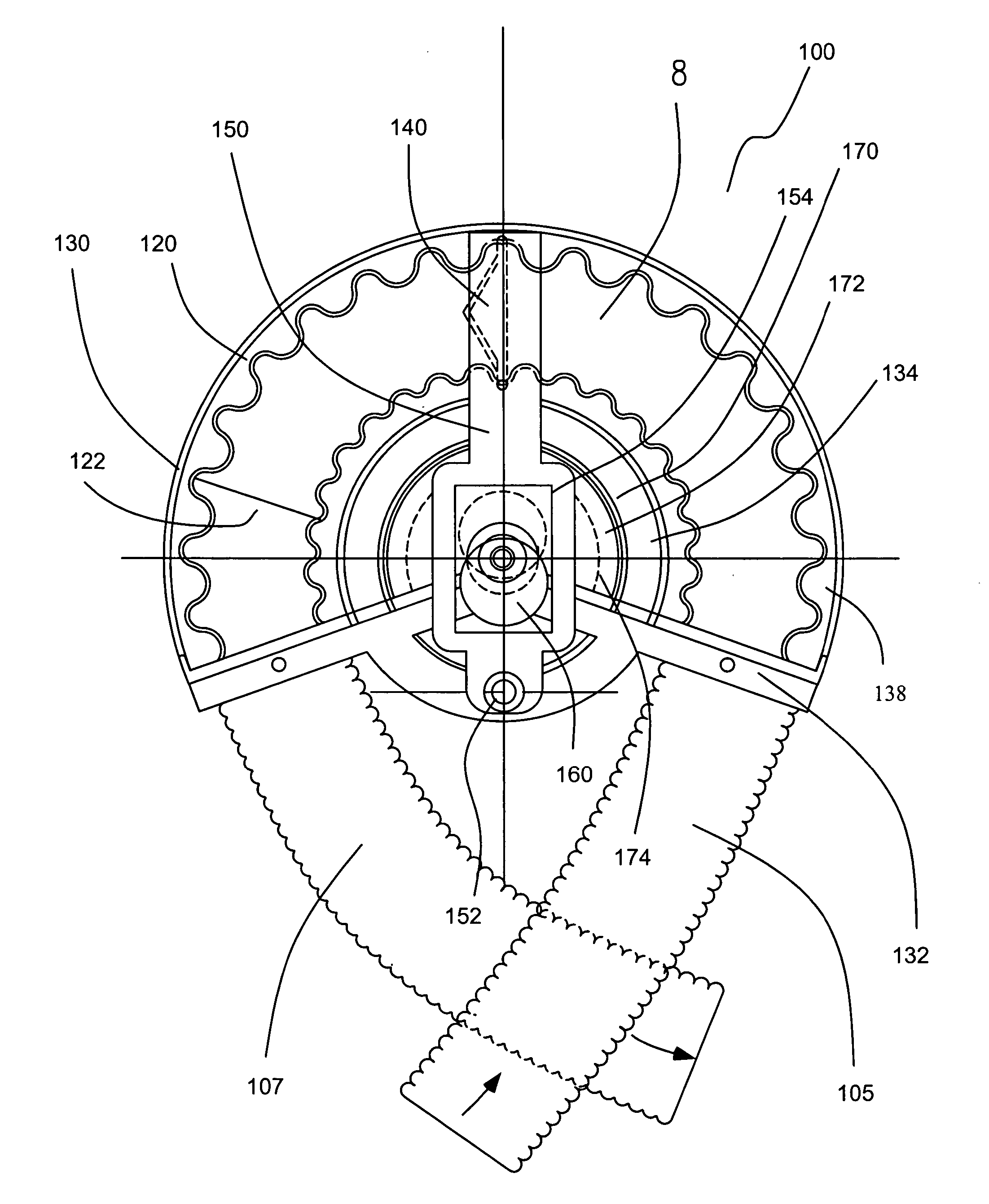
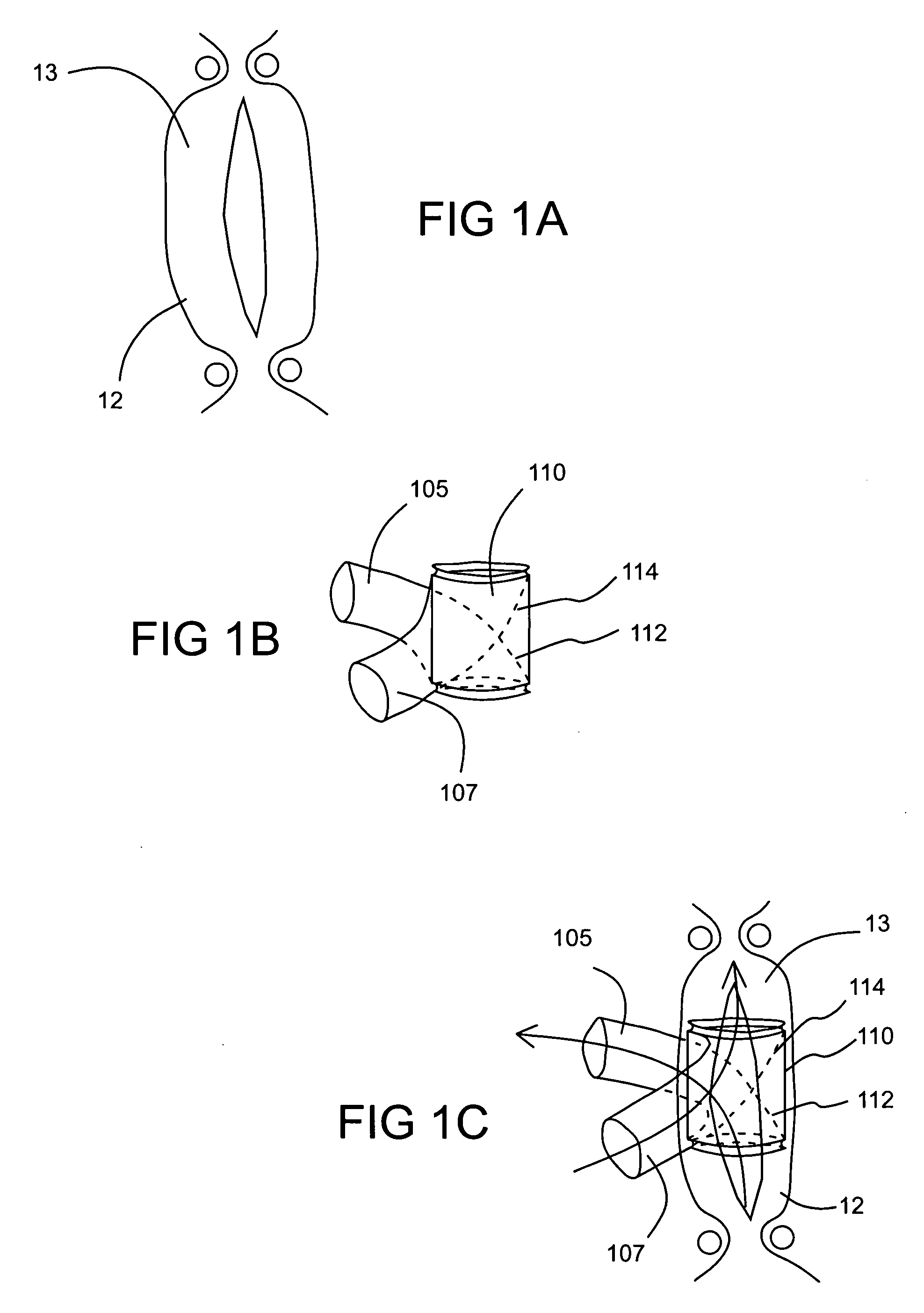
[0054] The pumps of the present invention can, for example, assist or augment cardiac output via in-series placement with a blood vessel such as the ascending aorta just above the heart of a patient suffering from heart disease. The pumps of the present invention can, for example, alternatively or additionally be placed in series connection with the pulmonary artery. In several embodiments of the pumps of the present invention, a multi-stroke or oscillating valve is used to induce blood flow. As used herein, the term “multi-stroke” refers to a valve that oscillates (that is, moves forward and rearward) more than once for each left ventricle contraction.

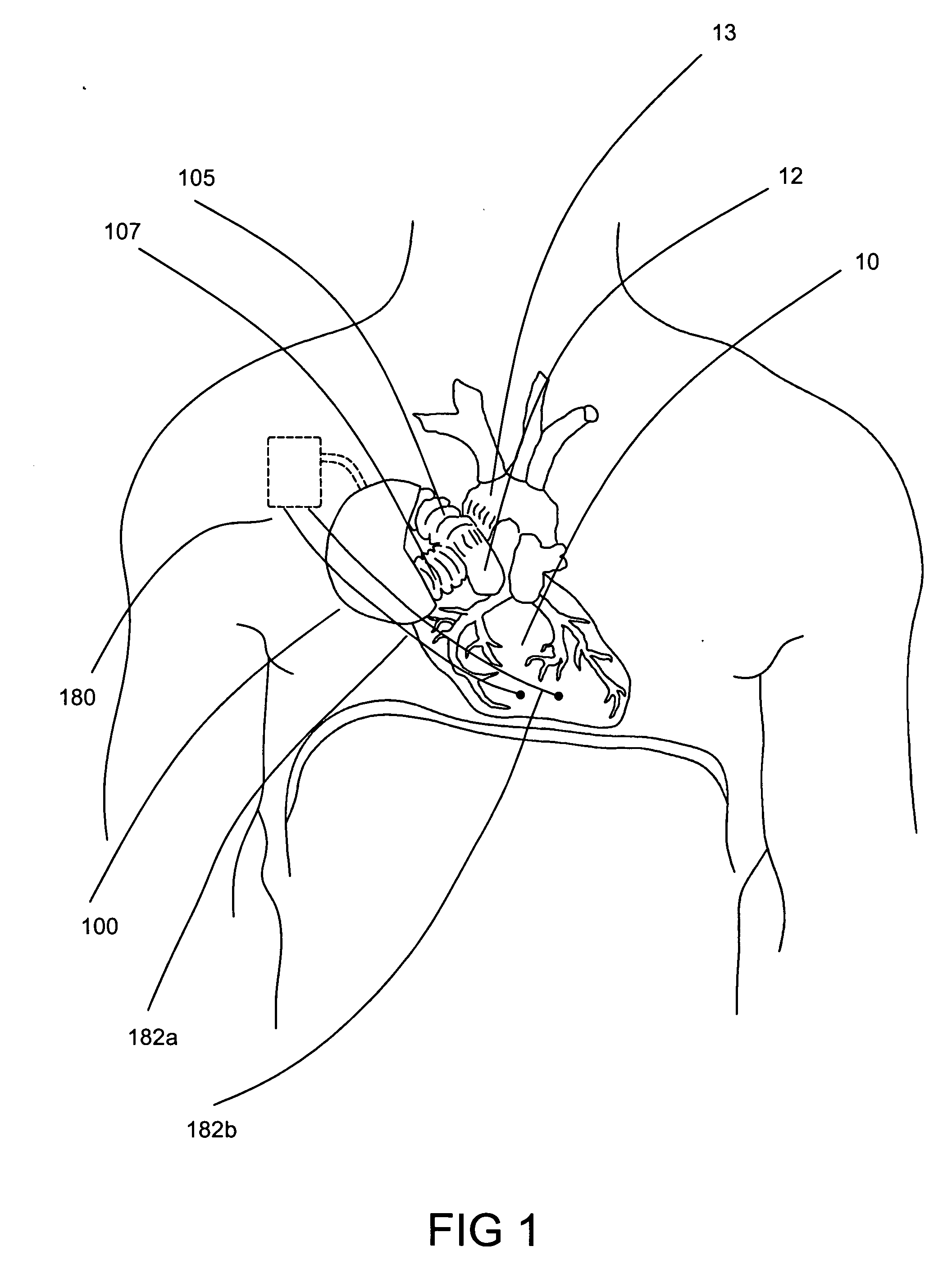
[0055] Referring now to the drawings, wherein like reference numerals refer to the same item, there is shown in FIG. 1 a pump 100 connected to the ascending aorta at the output of the patients heart 10. In a fully implanted pump configuration as illustrated in FIG. 1, the pump 100 is be placed close to the ascending aorta in the uppe...


PUM


Abstract

A pump includes a flexible conduit, at least one valve attached to the flexible conduit about the perimeter of the valve; and a drive mechanism to move the valve to pump blood within the conduit. The drive mechanism can, for example, be adapted to complete a single stroke during each heart ventricle contraction and/or to complete multiple strokes (that is, oscillate) during a single contraction. Another implantable pump for assisting blood flow, includes: a flexible conduit formed in an arc; at least one movable valve in operative connection with the conduit; and a drive mechanism to move the valve in an arced path to pump blood within the conduit. Another pump includes a conduit and at least one moveable valve within the conduit. The moveable valve includes a plurality of openings. Each of the plurality of openings has a closure mechanism in operative connection therewith. Each closure mechanism is operable to at least partially close the opening to which it is operatively connected when the moveable valve is moved forward and to open the opening to which it is operatively connected when the valve is move rearward. The pump further includes a drive mechanism to move the valve to pump blood within the conduit. In one embodiment, each closure mechanism includes a flap of resilient material.

Description

CROSS-REFERENCE TO RELATED APPLICATION [0001] This application claims benefit of U.S. Provisional Patent Application No. 60 / 589,044, filed Jul. 19, 2004, the disclosure of which is incorporated herein by reference,BACKGROUND OF THE INVENTION [0002] The present invention relates generally to devices, systems and methods for assisting blood flow, and, particularly, to blood pumps that include a moving (for example, an oscillating) valve assembly to propel blood. The pumps of the present invention can be either fully implanted or temporarily connected to the circulation using percutaneous blood conduits. The pumps of the present invention can, for example, be fully or completely implanted for months to years to alleviate or correct heart failure and related symptoms. [0003] Heart failure, or the inability of the heart to pump sufficient blood for the body's needs, results in very poor quality of life, huge costs to society, and hundreds of thousands of yearly deaths. Heart failure is c...

Claims


Application Information

Patent Timeline
IPC IPC(8): A61M1/10A61M60/178A61M60/268A61M60/427A61M60/441A61M60/515A61M60/538A61M60/857
CPCA61M1/1037A61M1/1046A61M1/106A61M1/1086A61M1/122A61M1/1049A61M1/1055A61M1/1098A61M1/1041A61M60/284A61M60/892A61M60/896A61M60/148A61M60/427A61M60/178A61M60/538A61M60/441A61M60/515
Inventor HEILMAN, MARLIN STEPHENKOEBLER, DOUGLAS J.MOORE, DANIEL R.PREM, EDWARD K.
Owner HEILMAN MARLIN STEPHEN
Why Eureka
Try Eureka