
Exposure technique

a technology of exposure and spherical filter, applied in the field of exposure techniques, can solve the problems of increasing the time required for the whole initial purge, disadvantageous time required for the initial purge, and increasing the time required for the initial purge, and achieves the effects of high purity, high productivity, and low running cos

Inactive Publication Date: 2006-02-16
CANON KK
View PDF8 Cites 22 Cited by
  • Summary
  • Abstract
  • Description
  • Claims
  • Application Information

AI Technical Summary

Benefits of technology

[0030] According to the present invention, in an exposure apparatus using ultra violet rays such as fluorine excimer laser beams, an inert gas atmosphere having a high purity can be obtained within a short period of time by supplying a small amount of an inert gas, and as a result, high productivity and inexpensive running cost can be simultaneously realized.

Problems solved by technology

However, in the case of the related device described above, there has been a problem in that a time required for changing the state in which the airtight chamber 1 and the air conditioner 4 are sufficiently exposed to the atmosphere to the state of a predetermined inert gas atmosphere is very long, that is, a time required for an initial purge is disadvantageously very long.
As described above, of the two paths in which the replacement is performed with an inert gas, the replacement is dominantly carried out by a diffusion phenomenon in one of the two paths, and as a result, a very long time is required for the initial purge on the whole.
Accordingly, the time required for startup of an apparatus is increased, and as a result, the productivity thereof is disadvantageously degraded.
In addition, a large amount of moisture is adsorbed onto surfaces of substances exposed to the atmosphere.
In particular, since many resins have hydrophilic properties or moisture absorption properties, moisture is unlikely to be desorbed from the surface of a resin as compared to the surface of a metal, and hence a problem may arise in that a large amount of moisture adsorbed on a resin is continuously desorbed for a long period of time.
Hence, in a reticle space or a wafer space in which resin members are inevitably provided, even when the purge is performed with an inert gas having a high purity, moisture adsorbed onto the surface of the materials is gradually being desorbed for a long period of time, and as a result, it will take several tens of hours to enable the moisture to reach a predetermined concentration.
Accordingly, the time required for startup of an apparatus is increased, and as a result, the productivity thereof is disadvantageously degraded.
Furthermore, in order to obtain a predetermined moisture concentration, a larger amount of an inert gas having a high purity must be continuously supplied from the supply source, and as a result, the running cost of the apparatus is disadvantageously increased.
Furthermore, since a glass or a fluorinated resin is used as the filter medium, a large amount of moisture adsorbed onto the surface thereof is disadvantageously being desorbed for a long period of time.
As a filter media of the chemical filter, for example, an ion exchange resin, granular or fabric active carbon, or an inorganic ceramic may be used; however, as is the case of the dust collector filter described above, since the surface area thereof is large, and as a result, a large amount of moisture adsorbed onto the surface of the filter medium is disadvantageously being desorbed for a long period of time.
Accordingly, the time required for startup of the apparatus is increased, and as a result, the productivity thereof is disadvantageously degraded.
Furthermore, in order to obtain a predetermined moisture concentration, a larger amount of an inert gas having a high purity must be continuously supplied from the supply source, and as a result, the running cost of the apparatus is disadvantageously increased.
In addition, besides moisture, impurities in the atmosphere and in a clean room may be adsorbed onto filters and the like during the transportation and the assembly in some cases, and as a result, the impurities themselves or those dissolved in moisture adsorbed on the surfaces of the filters and the like disadvantageously behave in the same manner as that of the moisture described above.
In addition, when maintenance or repair of various units placed in a reticle space or a wafer space is performed, the space must be exposed to the atmosphere.
As a result, exterior moisture and impurities are again adsorbed onto the surfaces of the filter media of the filters, and even when the purge is re-started using an inert gas after the maintenance is completed, a long period of time and a large amount of an inert gas having a high purity are required to obtain a predetermined moisture concentration and impurity concentration, and as a result, the degradation in productivity of the apparatus and rapid increase in running cost thereof disadvantageously occur.
Otherwise, the productivity required for an exposure apparatus cannot be ensured.
This increase in concentration of the moisture and impurities causes the degradation in transmittance in an exposure light atmosphere and the generation of haze of optical members, and as a result, a problem may arise in that the productivity of the exposure apparatus is degraded.

Method used


Image

  • Exposure technique
  • Exposure technique
  • Exposure technique

Examples


embodiment 1

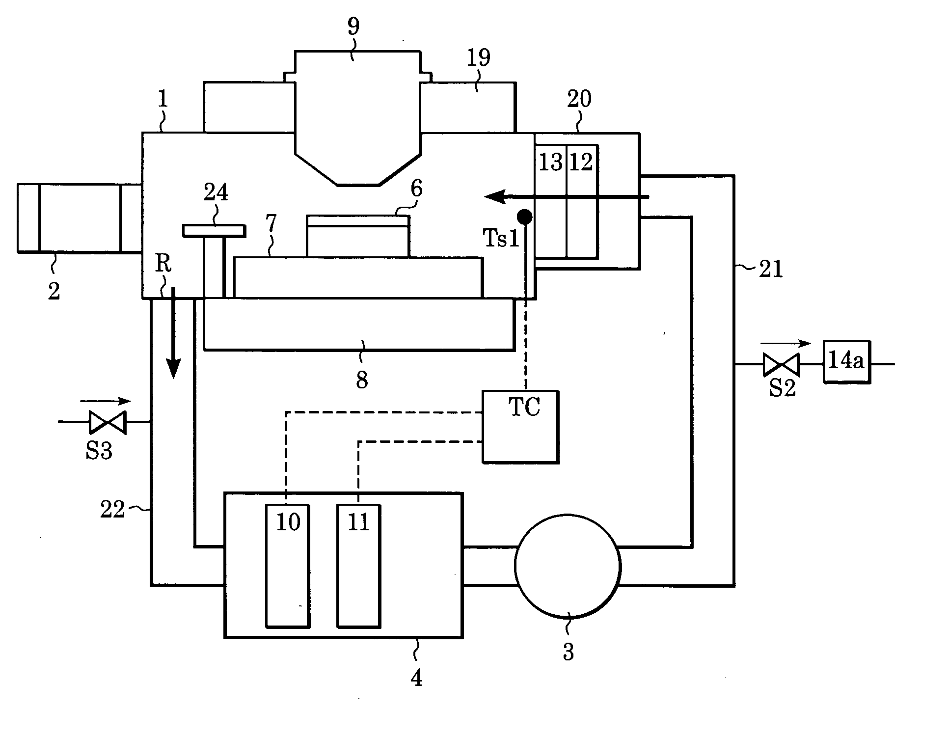
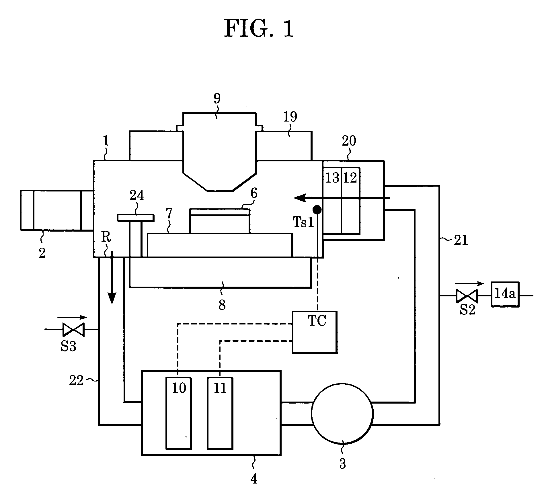
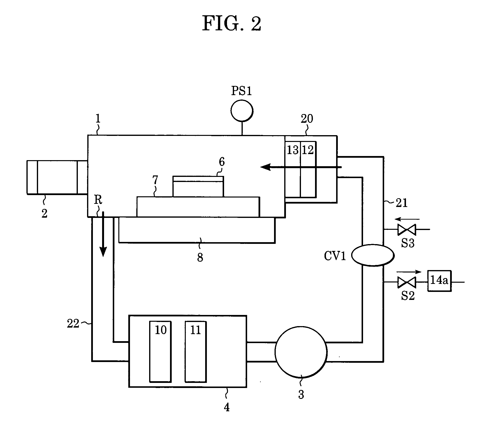
[0043]FIGS. 2 and 3 are schematic views each showing a gas circulating air-conditioning device (atmosphere control device) as an inert gas circulating device of an exposure apparatus according to Embodiment 1 of the present invention. The same reference numerals of the constituent elements of the inert gas circulating device in FIG. 1 shown as the case of the related device designate the same constituent elements of this embodiment, and description thereof will be omitted. In addition, the projection optical system 9, the structural member 19, the wafer transfer system 24, the temperature sensor Ts1, and the temperature control device TC are not shown in the figure and will not be described. This embodiment will be described using the airtight chamber 1 which receives a wafer side by way of example. However, the same situation as the case mentioned above can be naturally contemplated at a reticle side. The airtight chamber 1 is approximately sealed from the exterior atmosphere and i...

embodiment 2

[0051]FIG. 4 is a schematic view showing a gas circulating air-conditioning device as an inert gas circulating device of an exposure apparatus according to Embodiment 2 of the present invention. Unlike the case of Embodiment 1 shown in FIG. 3, in this embodiment, filters such as the dust collector filter 13 and the chemical filter 12 provided at the airtight chamber 1 side are received in a filter box 5 which is a separate housing formed so that a gas in the space thereof can be independently replaced with an inert gas. In addition, unlike the case shown in FIG. 3, a circulation path valve CV2 is provided in a circulation relay path 23 connecting between the air conditioner 4 and the filter box 5, and an inert gas exhaust path S4 and an inert gas supply path S1 are provided upstream and downstream of the circulation path valve CV2. In FIG. 4, when the circulation path valves CV1 and CV2 are closed, the airtight state of the space in the filer box 5 can be maintained, and furthermore...

embodiment 3

[0056]FIG. 5 is a schematic view showing a gas circulating air-conditioning device as an inert gas circulating device of an exposure apparatus according to Embodiment 3 of the present invention. Unlike the Embodiment 2 shown in FIG. 4, in this embodiment, there are provided a heating device 15 as a filter heating device for heating the filters received in the filter box 5, a temperature sensor Ts2 for sensing a temperature in the filter box, and a temperature control device 16 for controlling an output of the heating device 15 to set the temperature sensed by the temperature sensor Ts2 to a predetermined value, so that a function of depleting moisture is additionally formed in which moisture adsorbed onto the filters are removed outside by heating. In addition, as shown in FIG. 5, there are provided a drain line S7 communicating with the filter box 5, a drain tank 25 connected to the drain line S7, and valves V1 and V2 connected to two ends of this drain tank 25, so that when gather...


PUM


Abstract

An atmosphere control technique for an exposure apparatus. An exposure apparatus to which this technique is applied includes, for example, a chamber which contains a space through which exposure light passes, a circulation system which has a path and circulates an inert gas through the path and the chamber, at least one valve provided in the path, a supply system which has a supply port at one end of a zone of the path defined by the at least one valve and supplies an inert gas to the supply port, and an exhaust system which has an exhaust port at the other end of the zone and exhausts a gas from the exhaust port.

Description

[0001] This application claims priority from Japanese Patent Application No. 2003-374100, entitled “EXPOSURE APPARATUS AND ENVIRONMENTAL CONTROL METHOD” and filed on Nov. 4, 2003, the entire contents of which are incorporated herein by reference. BACKGROUND OF THE INVENTION [0002] 1. Field of the Invention [0003] The present invention relates to exposure techniques, and more particularly, relates to an atmosphere control technique which controls an atmosphere in an airtight chamber of an exposure apparatus by circulating an inert gas having a predetermined purity. [0004] 2. Description of the Related Art [0005] Hitherto, in manufacturing of a semiconductor element such as an LSI or a VLSI having a ultra fine pattern, a reduction type projection exposure apparatus has been used in which a circuit pattern drawn in a mask is formed onto a substrate coated with a photosensitive agent by printing using a reduction projecting technique. Concomitant with the improvement in packaging densit...

Claims


Application Information

Patent Timeline
IPC IPC(8): G03B27/52H01L21/027G03F7/20H01L21/677H01L21/68
CPCG03F7/70933
Inventor NAKANO, HITOSHI
Owner CANON KK
Learn More