Electronic device having a temperature control system including a ductwork assembly

a technology of temperature control system and electronic device, which is applied in the direction of incadescent cooling arrangement, discharge tube main electrode, television system, etc., can solve the problems of significant temperature rise in the device, significant panel heating, and inability to stably operate the driven oled display in such applications

Active Publication Date: 2006-02-16
LG CHEM LTD
View PDF30 Cites 76 Cited by
  • Summary
  • Abstract
  • Description
  • Claims
  • Application Information

AI Technical Summary

Problems solved by technology

When thermal conduction from the emission layer to the surroundings is not sufficient, substantial panel heating will occur.
In such cases, if the heat flowing from the radiation-emitting region to the ambient air is insufficient, a significant temperature rise will also take place in the device.
AM-driven OLED displays in such applications may not be stably operated at such high brightness levels, and the temperature may not even be stabilized due to insufficient heat flow out of the device (a phenomenon known as thermal run-off).

Method used


Image

  • Electronic device having a temperature control system including a ductwork assembly
  • Electronic device having a temperature control system including a ductwork assembly
  • Electronic device having a temperature control system including a ductwork assembly

Examples


first embodiment

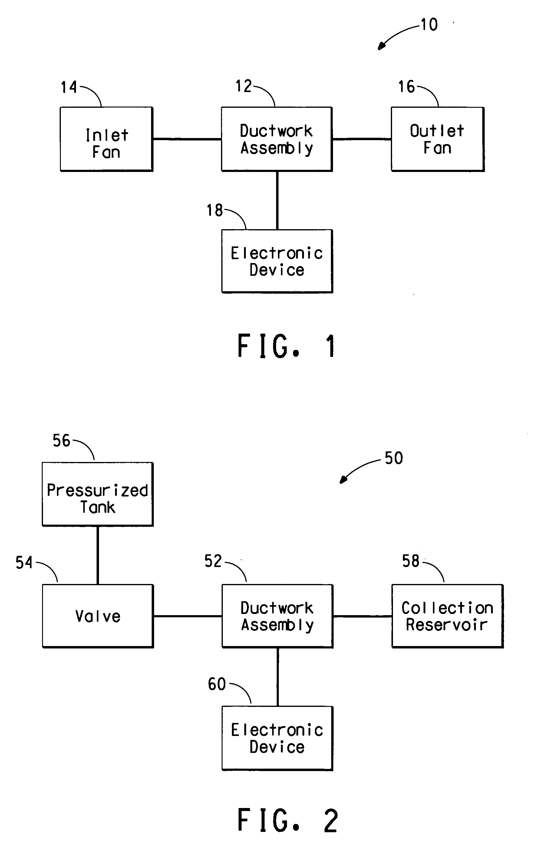
[0084] Referring initially to FIG. 1, a temperature control system for an electronic device is depicted and is generally designated 10. As depicted in FIG. 1, the temperature control system includes a ductwork assembly 12 to which an inlet fan 14 can be fluidly connected, e.g., to an inlet end established by the ductwork assembly 12. The ductwork assembly 12 can be any of the ductwork assemblies described in conjunction with FIG. 4 through FIG. 18. Note that temperature control systems including ductwork assemblies are not limited only to those illustrated in FIG. 4 through FIG. 18. After reading this specification, skilled artisans will be able to apply other temperature control systems with ductwork assemblies that fit their particular needs or desires.

[0085]FIG. 1 further illustrates that an outlet fan 16 can also be fluidly connected to the ductwork assembly 12, e.g., to an outlet end established by the ductwork assembly 12. Moreover, as illustrated, the ductwork assembly 12 can...

second embodiment

[0087]FIG. 2 depicts a temperature control system, generally designated 50. As depicted in FIG. 2, the temperature control system 50 includes a ductwork assembly 52, e.g., one or more of the ductwork assemblies described in detail below. A valve 54 is fluidly connected to the ductwork assembly 52, e.g., to an inlet end established by the ductwork assembly 52. In one embodiment, the valve 54 is a regulator valve. In turn, a pressurized tank 56 is fluidly connected to the valve 54. The pressurized tank 56 can include a heat transfer fluid as a liquid, a compressed gas, or a supercritical fluid. In one embodiment, the heat transfer fluid within the pressurized tank 56 can be nitrogen, carbon dioxide, a noble gas (e.g., helium, neon, argon, krypton xenon, radon), other relatively inert gas, or any combination thereof and can be stored in the pressurized tank 56. FIG. 2 further illustrates a collection reservoir 58 that can be fluidly connected to the ductwork assembly 52, e.g., to an ou...

third embodiment

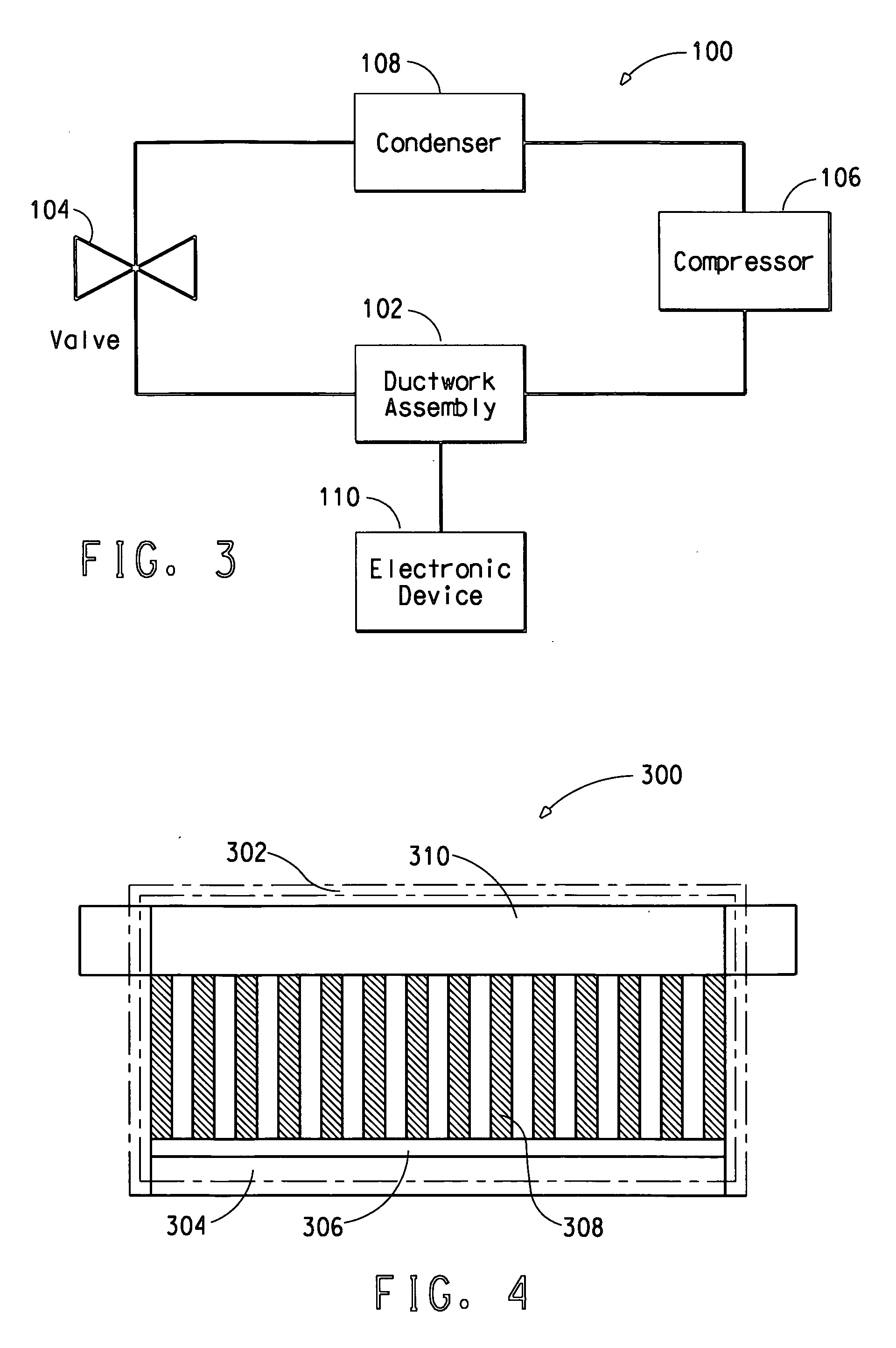
[0089] Referring now to FIG. 3, a temperature control system is portrayed and is generally designated 100. As depicted in FIG. 3, the system includes a ductwork assembly 102 to which a valve 104, such as an expansion valve, is fluidly connected, e.g., to an inlet end established by the ductwork assembly 102. A compressor 106 is fluidly connected to the ductwork assembly 102, e.g., to an outlet end formed by the ductwork assembly 102. Further, the valve 104 is fluidly connected to the compressor 106 via a condenser 108. Thus, a closed loop is established by the valve 104, the ductwork assembly 102, the compressor 106, and the condenser 108. FIG. 3 also illustrates an electronic device 110 that is thermally coupled to the ductwork assembly 102. As described below, the electronic device 110 can be cooled by the ductwork assembly 102.

[0090] In one embodiment, the closed loop, established by the valve 104, the ductwork assembly 102, the compressor 106, and the condenser 108, can include ...


PUM


Abstract

A ductwork assembly can be used with an electronic device wherein the electronic device includes a fan and the ductwork assembly is configured to receive a heat transfer fluid from the fan. A disperser lies within the ductwork assembly and is attached thereto in order to affect at least a portion of a flow of the heat transfer fluid. The duckwork assembly may also include a first channel and the first channel is characterized by a first average fluid veloicty that is a hightest average fluid velocity of all channels within the ductwork assembly. The ductwork assembly may include a second channel that is characterized by a second average fluid veloicty that is a lowest average fluid velocity of all channels within the ductwork assembly. The second averaged fluid velocity may be no less than 90% of the first averaged fluid velocity.

Description

FIELD OF THE INVENTION [0001] The invention relates in general to electronic devices, and more particularly to electronic devices having temperature control systems including ductwork assemblies. BACKGROUND INFORMATION [0002] Electronic devices, including organic electronic devices, continue to be used more extensively in everyday life. Examples of organic electronic devices include Organic Light-Emitting Diode (“OLED”) displays. The radiation emission efficiencies of OLEDs are typically in a range of approximately one to twenty candelas per ampere (1-20 cd / A). For a full-color display with a fifty percent (50%) aperture ratio and with a circular polarizer with approximately forty percent (40%) optical transmission, the current density is in a range of approximately thirty to six hundred milliamperes per square centimeters (30-600 mA / cm2) for an emission intensity of approximately 400 cd / m2. At an operation voltage of approximately five volts (5 V), the corresponding input electric ...

Claims


Application Information

Patent Timeline
Patent Type & Authority Applications(United States)
IPC IPC(8): H05K7/20
CPCH05K7/20209H05K7/20145
Inventor WANG, JIANYU, GANG
Owner LG CHEM LTD
Why Eureka
Try Eureka