
Optical diagnostics integrated with laser spark delivery system

a laser and laser technology, applied in the direction of optical radiation measurement, instruments, spectrometry/spectrophotometry/monochromators, etc., can solve the problems of cylinder pressure and mixture density in modern engines, affecting the efficiency of laser spark generation, etc., to achieve the effect of reducing early flame growth and facilitating spark creation with laser

Active Publication Date: 2006-02-23
COLORADO STATE UNIVERSITY
View PDF24 Cites 77 Cited by
  • Summary
  • Abstract
  • Description
  • Claims
  • Application Information

AI Technical Summary

Benefits of technology

The present invention provides a new system and method for controlling electronic devices using handheld controllers. The system includes a handheld controller with a touch screen and a Bluetooth connection. The controller can communicate with the electronic device using Bluetooth, and the device can be controlled using the touch screen. The system allows for easy and intuitive control of electronic devices, making it more convenient and user-friendly.

Problems solved by technology

The electron collision will ionize the atom, producing additional electron(s) to start the cascade process and lead to avalanche breakdown.
Therefore, there tends to be some uncertainty in published intensity requirements for breakdown and spark formation.
For sparking uses associated with combustion engines, the desired combination of lean mixtures and high brake mean effective pressure results in the cylinder pressure and mixture density in modern engines being relatively high, creating difficulties for traditional spark ignition systems.
As the density increases in the cylinder, the breakdown voltage (minimum voltage required to form a spark using a spark ignition system) also increases, ultimately to such high voltage levels that traditional spark ignition systems encounter problems with dielectric breakdown leading to unwanted sparking from the ignition leads and other undesired locations (i.e., the spark does not form between the electrodes as intended).
Even if the high voltage can be managed, high voltage means that electrode erosion can be quite high.
The combination of spark plug erosion and dielectric breakdown is a limiting factor in the operational envelope of modern gas engines.
Although simple and effective, this system is not practical for most industrial applications.
The key challenges associated with the use of fiber optic delivery are the intensity damage threshold of the fiber optic material and limitations on focusing fiber optically delivered light.
Because the intensity at the fiber exit is limited, the imaging or focusing requirements to generate a sufficient intensity to spark at the desired spark location become more stringent.
The problem is compounded by the second challenge which is the difficulty in focusing fiber optically delivered light.
This increase in spot size, which makes it more difficult to reach high intensity, is related to a degradation of the spatial quality of a laser beam caused by transmission through a fiber.
For small-diameter single-mode fibers (diameter<˜30 μm) the degradation is minimal; however, such fibers cannot transmit a large amount of energy and are not considered useful in laser ignition application(s).
Larger diameter fibers are required to transmit higher energies, but in such cases the larger diameter increases the beam degradation and thus impedes focusing to small spot sizes (high intensities).
Such a configuration has a higher index in the wall than the core and does not allow efficient light guiding.
It is noted that it is much more difficult to form a spark in the gas phase as compared to on a solid or in a liquid because more optical intensity is required.
However, it is desirable to spark in the gas phase because it allows the spark to be located away from cylinder walls or other solid surfaces, which act as heat sinks and yield poorer combustion performance.
Another consequence of the ease of sparking on solids is that the use of fiber optics becomes harder because of the tendency to spark (unwantedly) at the launch entrance of the fiber.
Such sparks consume energy from the laser beam and may degrade the quality of the beam preventing subsequent sparking after the fiber.
In general, ordinary solid core fibers suffer from degradation of the quality of the laser light as it travels through them, as well as intensity limits and difficulties of launching the input light.
Fiber lasers, however, may circumvent these problems and are capable of delivering high-quality and high-intensity laser pulses.
However, among other things, this reference fails to disclose the combination of providing a spark and measuring diagnostic light.
However, among other things, these references also fail to disclose the combination of providing a spark and measuring diagnostic light.
However, solid silica core fibers are not suitable for generating a spark in air and / or in fuel air mixtures inside an engine, as explained above.

Method used


Image

  • Optical diagnostics integrated with laser spark delivery system
  • Optical diagnostics integrated with laser spark delivery system
  • Optical diagnostics integrated with laser spark delivery system

Examples


Embodiment Construction

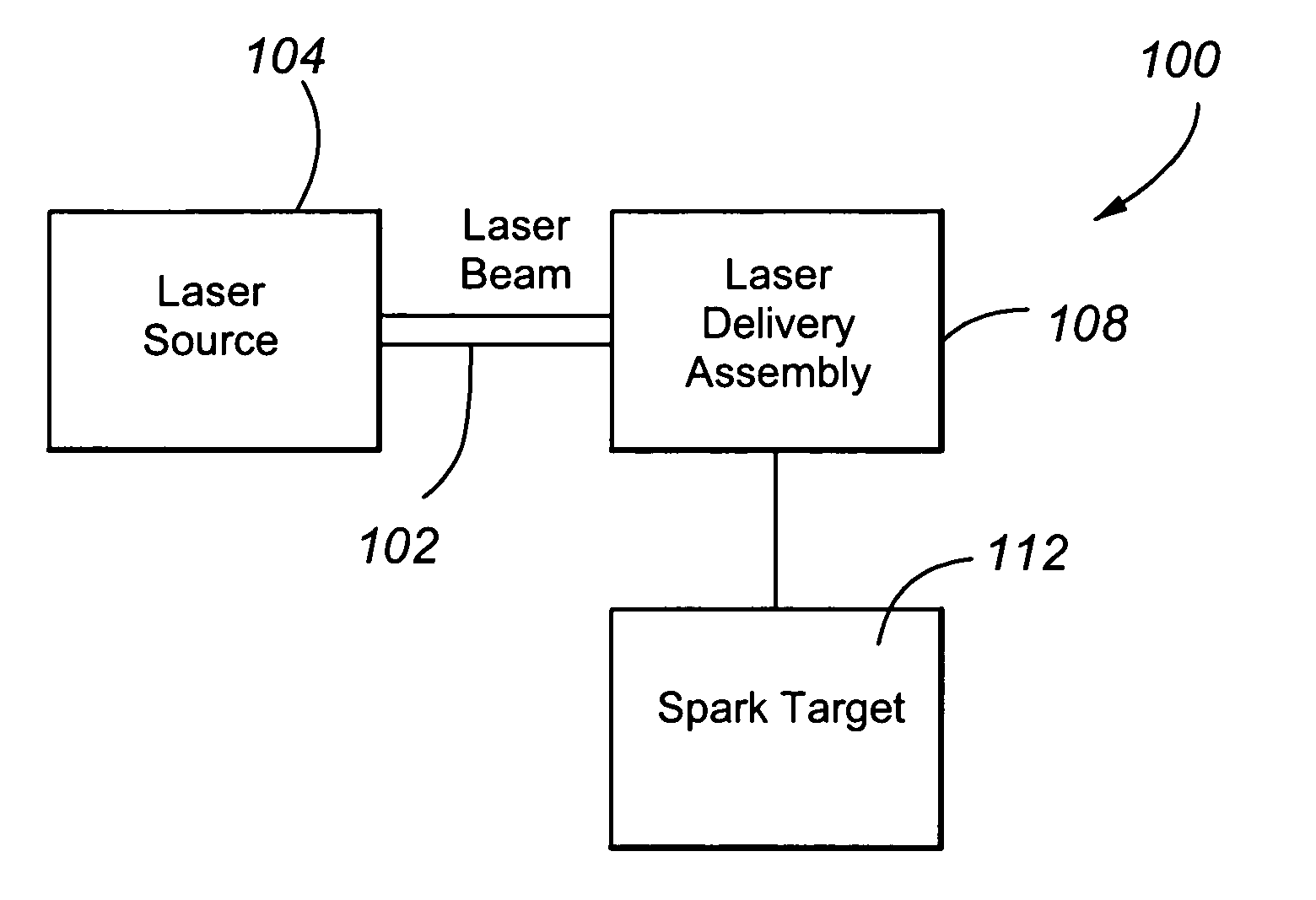
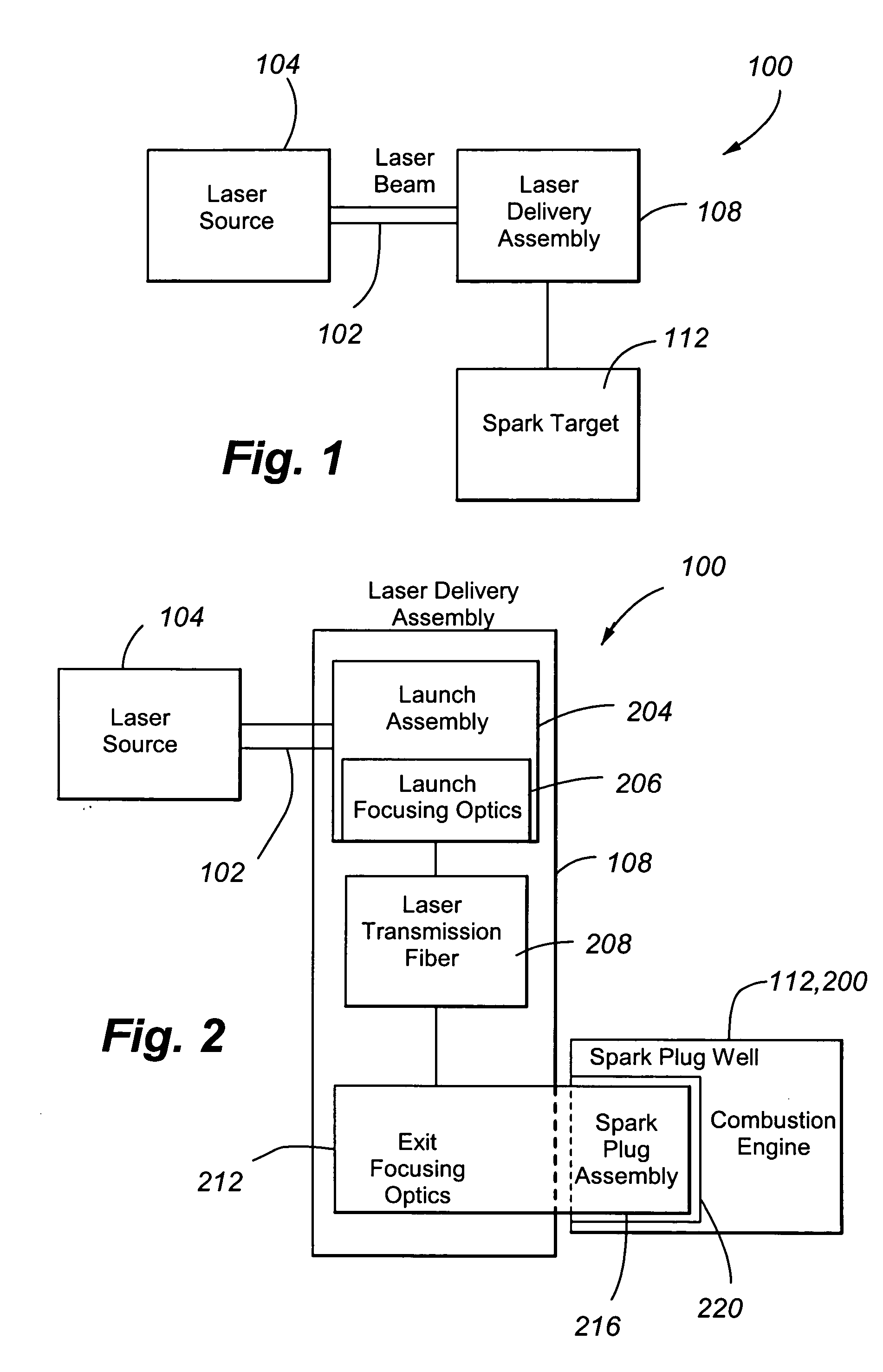
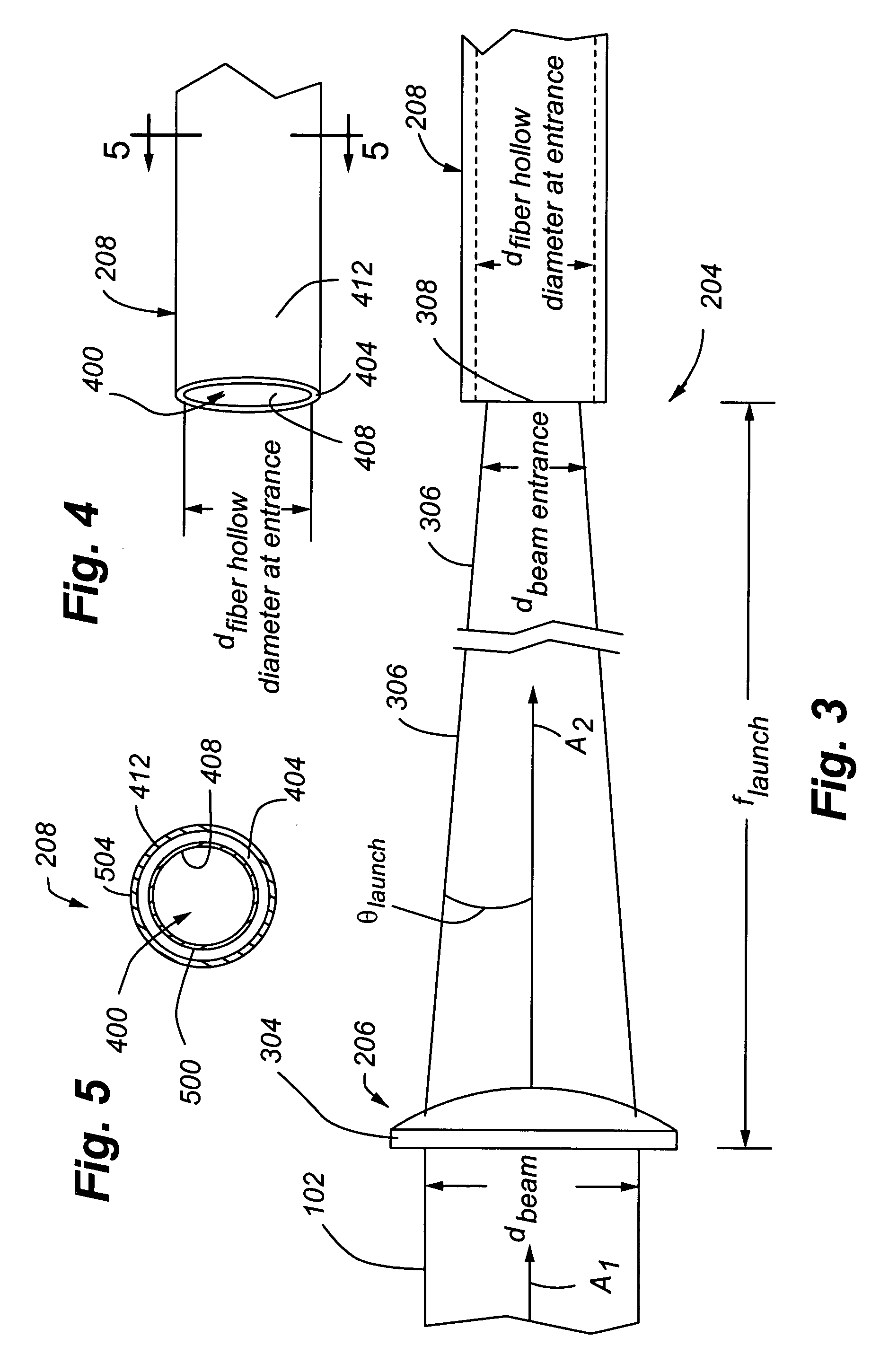
[0052]FIG. 1 illustrates a spark delivery system 100 in accordance with embodiments of the present invention. The system 100 generally includes a laser source 104 in optical communication with a laser delivery assembly 108, which in turn is in optical communication with a spark target 112. The laser source 104 provides a beam of laser light 102 to the laser delivery assembly 108. In order to provide a desirable launch, a laser source 104 with a relatively high spatial quality is desirable. It is estimated that a laser source 104 with a spatial quality M2 parameter of less than about 10 is required. In accordance with embodiments of the present invention, and by way of example and not limitation, a laser source 104 such as a Continuum 8050. Nd:YAG laser has been found to provide an acceptable laser beam 102 for sparking. In accordance with embodiments of the present invention, and by way of example and not limitation, a wavelength of 1064 nm has been found sufficient for sparking; ho...


PUM


Abstract

A spark delivery system for generating a spark using a laser beam is provided, and includes a laser light source and a laser delivery assembly. The laser delivery assembly includes a hollow fiber and a launch assembly comprising launch focusing optics to input the laser beam in the hollow fiber. The laser delivery assembly further includes exit focusing optics that demagnify an exit beam of laser light from the hollow fiber, thereby increasing the intensity of the laser beam and creating a spark. Other embodiments use a fiber laser to generate a spark. Embodiments of the present invention may be used to create a spark in an engine. Yet other embodiments include collecting light from the spark or a flame resulting from the spark and conveying the light for diagnostics. Methods of using the spark delivery systems and diagnostic systems are provided.

Description

CROSS REFERENCE TO RELATED APPLICATIONS [0001] The present application is a continuation-in-part application of U.S. patent application Ser. No. 11 / 126,908 filed May 10, 2005, which claimed the benefit of U.S. Provisional Patent Application No. 60 / 598,932 filed on Aug. 4, 2004; in addition, the present application claims the benefit of U.S. Provisional Patent Application No. 60 / 598,932 filed on Aug. 4, 2004. The entire disclosures of the above-referenced patent applications are incorporated herein by reference in their entirety. Cross reference is also made to U.S. patent application Ser. No. ______ (U.S. Express Mail No. EV556792009US) filed on Aug. 4, 2005, entitled “FIBER LASER COUPLED OPTICAL SPARK DELIVERY SYSTEM,” the entire disclosure of which is incorporated herein by reference in its entirety. STATEMENT REGARDING FEDERALLY SPONSORED RESEARCH OR DEVELOPMENT [0002] This invention was made with United States Government support under Grant No. DE-FC26-02NT41335 awarded by the D...

Claims


Application Information

Patent Timeline
Patent Type & Authority Applications(United States)
IPC IPC(8): F02P23/00G01J3/30
CPCF02D35/022F02P17/12G01N2201/08G01N21/718F02P23/04
Inventor YALIN, AZERWILLSON, BRYANDEFOORT, MORGANCOLLINS, GEORGE
Owner COLORADO STATE UNIVERSITY
Learn More