Ceramic impregnated superabrasives

a technology of ceramic impregnating and superabrasives, which is applied in the direction of ceramicware, carbides, other chemical processes, etc., can solve the problems of reducing the durability increasing the risk of cracking at void volumes more than approximately 7 percent, and affecting the performance of the resulting compact, so as to achieve significant different modulus and reduce the surface area of the preform

Inactive Publication Date: 2006-03-02
RADTKE ROBERT P +1
View PDF18 Cites 37 Cited by
  • Summary
  • Abstract
  • Description
  • Claims
  • Application Information

AI Technical Summary

Benefits of technology

[0026] The mechanical properties of the ceramic pore liner should complement those of the preform. The pore linings are preferably composed of more that one layer. Alternating layers should have significantly different modulus. For example, SiOC ceramic formed from Blackglas has a modulus that is approximately 35 percent of that of SiC ceramic that is formed from Ceraset. Further, SiC has a modulus that is approximately 50 percent of that of TSP diamond or cubic boron nitride. Ceraset is a trademark of KiON Corporation, and is applied to a liquid pre-ceramic polyureasilazane. The modulus of any layer of the pore lining should be at least about 1...

Problems solved by technology

Where preforms with more than approximately 10 percent void volume are used, the impregnation pressure tends to crack the preform.
There is some risk of cracking at void volumes of more than ap...

Method used


Image

  • Ceramic impregnated superabrasives
  • Ceramic impregnated superabrasives
  • Ceramic impregnated superabrasives

Examples


Embodiment Construction

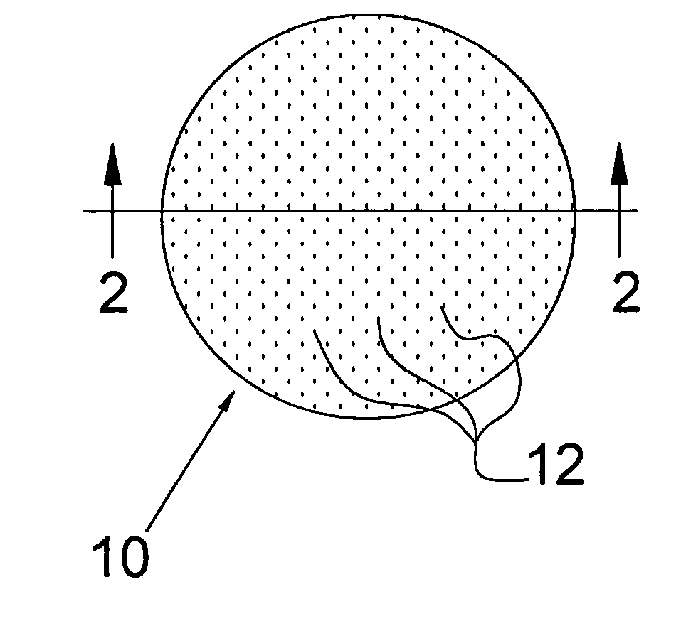
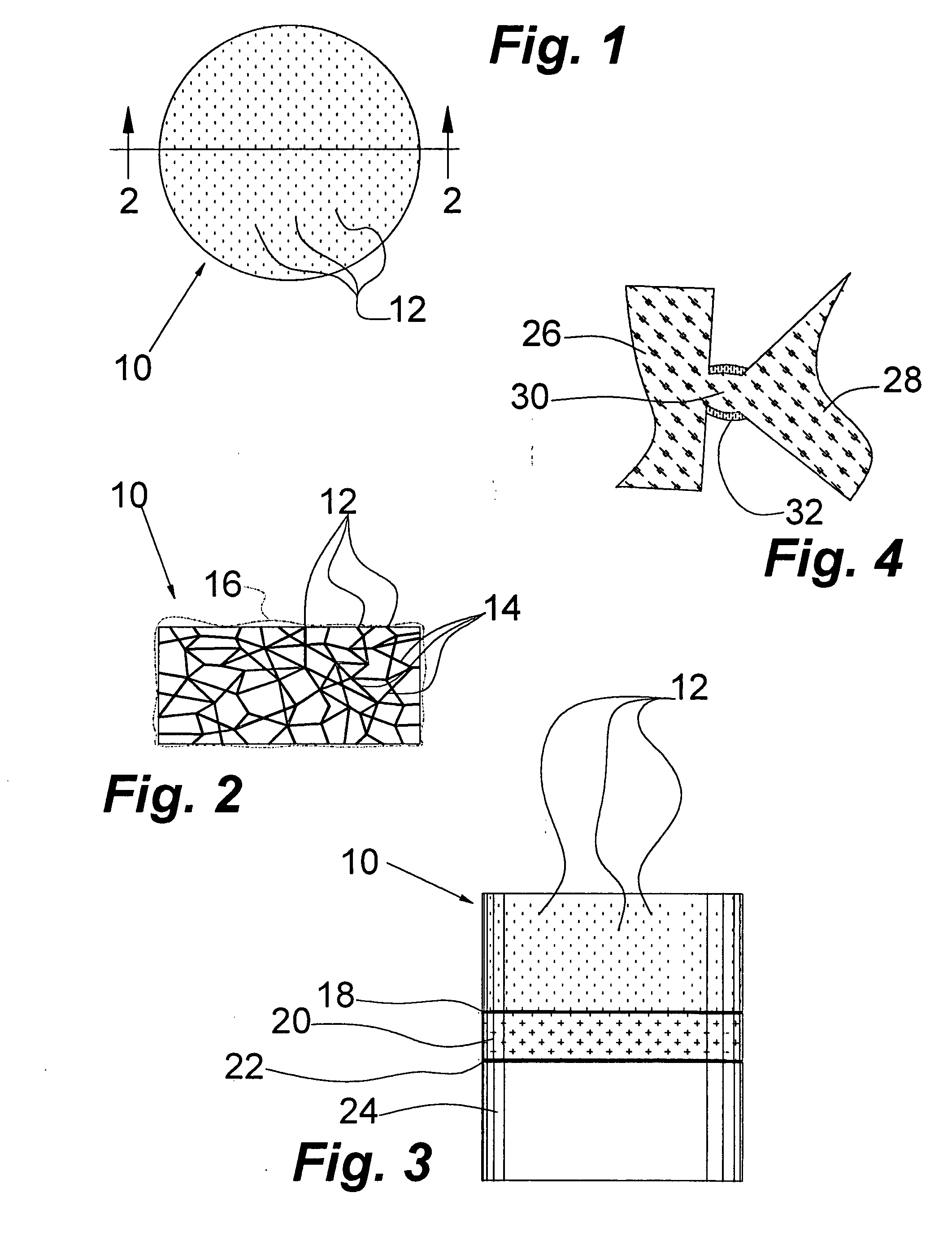
[0035] Referring now to the drawings wherein like reference numerals designate identical or corresponding parts throughout the several views, there is illustrated generally at 10 a ceramic impregnated polycrystalline superabrasive compact. The pores within the compact occur in a generally evenly distributed reticulated network 14 that is open to the environment at openings of which 12 are typical. In use, the ceramic impregnated superabrasive compacts 10 are brazed or otherwise bonded at 20 to a substrate 24, such as, for example, tungsten carbide mounting member 24. The thickness of the bond 20 has been exaggerated for the purposes of illustration. Bond 20 is generally much thinner than is illustrated. The braze or other bonding adheres well at 18 to the impregnated preform, and at 22 to the mounting member 24. Both bonds 18 and 22 must be secure or the attachment will fail.

[0036] Self bonded monolithic polycrystalline superabrasive preforms are typically bonded at a crystalline p...


PUM

PropertyMeasurementUnit
Fractionaaaaaaaaaa
Fractionaaaaaaaaaa
Fractionaaaaaaaaaa

Abstract

A superabrasive fracture resistant compact is formed by depositing successive layers of ceramic throughout the network of open pores in a thermally stable self-bonded polycrystalline diamond or cubic boron nitride preform. The void volume in the preform is from approximately 2 to 10 percent of the volume of the preform, and the average pore size is below approximately 3000 nanometers. The preform is evacuated and infiltrated under at least about 1500 pounds per square inch pressure with a liquid pre-ceramic polymerizable precursor. The precursor is infiltrated into the preform at or below the boiling point of the precursor. The precursor is polymerized into a solid phase material. The excess is removed from the outside of the preform, and the polymer is pyrolized to form a ceramic. The process is repeated at least once more so as to achieve upwards of 90 percent filling of the original void volume. When the remaining void volume drops below about 1 percent the physical properties of the compact, such as fracture resistance, improve substantially. Multiple infiltration cycles result in the deposition of sufficient ceramic to reduce the void volume to below 0.5 percent. The fracture resistance of the compacts in which the poes are lined with formed in situ ceramic is generally at least one and one-half times that of the starting preforms.

Description

STATEMENT REGARDING FEDERALLY SPONSORED RESEARCH OR DEVELOPMENT [0001] The U.S. Government has a paid-up license in this invention and the right in limited circumstances to require the patent owner to license others on reasonable terms as provided for by the terms of Program / Project Identification No. DE-FC276-97FT34368 awarded by National Energy Technology Laboratory, Morgantown, W. Va.BACKGROUND OF THE INVENTION [0002] 1. Field of the Invention [0003] The invention relates in general to superabrasive compacts, and, in particular, to compatible ceramic filled porous high temperature monolithic materials, such as, for example, self-bonded polycrystalline diamond or cubic boron nitride, which have improved fracture resistance and mechanical strength. The pores of a self-bonded preform are lined with multiple layers of ceramic deposited throughout the preform by successive cycles of liquid pre-ceramic impregnation-cure-pyrolysis. The layers may or may not be distinct from one another ...

Claims


Application Information

Patent Timeline
IPC IPC(8): C09K3/14C04B35/5831C04B41/52C04B41/89
CPCC04B35/52Y10T428/30C04B41/009C04B41/52C04B41/89C04B2235/3826C04B2235/3873C04B2235/3891C04B2235/3895C04B2235/427C04B2235/483C04B2235/616C04B2235/80C04B2235/96C04B35/5831C04B41/4521C04B41/4535C04B41/4554C04B41/457C04B41/5035C04B41/5059C04B41/5057C04B41/522C04B38/00Y10T428/249957Y10T428/249967Y10T428/249969C01B32/956E21B10/56E21B10/567
Inventor RADTKE, ROBERT P.SHERMAN, ANDREW
Owner RADTKE ROBERT P
Why Eureka
Try Eureka