Manufacturing method for joining multiple parts

a manufacturing method and technology for multiple parts, applied in the field of manufacturing methods for joining multiple parts, can solve the problems of difficult to achieve sufficient clamping, difficulty in welded connection, and increased difficulty in laser welding, so as to facilitate assembly and increase the usability of inventive arrangement

Inactive Publication Date: 2006-03-02
VOLVO CAR CORP
View PDF12 Cites 13 Cited by
  • Summary
  • Abstract
  • Description
  • Claims
  • Application Information

AI Technical Summary

Benefits of technology

[0009] Yet an object of this invention is to provide a manufacturing method for interconnecting vehicle body parts which can improve productivity, increase quality, be fit for mass production and reduce manufacturing cost.
[0010] The invention comprises a manufacturing method for interconnecting at least a first and a second body part of a sheet material to form a part of a vehicle body. The method comprises the steps of arranging the first and second body parts so that they essentially overlap and abut each other in an overlapping area, and exposing a welding zone of the overlapping area to a hybrid welding process in order to interconnect the first and second body parts in the overlapping area, the hybrid welding process comprising at least a first resistance seam welding step and a subsequent laser welding step. Hence, by this invention, the resulting weld will be a combination of a resistance seam weld and a laser weld. The first resistance seam welding step results in a preclamping of the first and second body part, and at the same time, the body parts are preheated so that any surface coatings, lubricants, sealants, adhesives and other residues are burned off, creating ideal conditions for the subsequent laser welding step. Thereby, this inventive method results in a strong, high quality weld, remarkably reducing the issues normally experienced with conventional laser welding.
[0012] A further advantage of this invention is that weld defects like porosity, undercut or even irregular weld geometry may be eliminated or strongly reduced, since the resistance seam welding step and the laser welding step may be balanced and optimised in such a way that any drawbacks experienced with any single one of the steps may be eliminated. Due to this, the resulting weld will be of high quality and have a high strength, which in turn enables higher stiffness and improved crash and fatigue properties for the weld. Also, the flange width of the body parts may be reduced, due to reduced space requirements of the welding tools used, as compared to for instance the commonly used resistance spot welding described above. This results in weight reductions of the overall vehicle. When used for upper body parts, such as in upper A, B or C pillar sections, this flange width reduction may also result in improved vision conditions.
[0013] Also, this inventive manufacturing method may be used for a new generation of extra strength and ultra high strength steel materials. For instance, this method may be used with any one of the following materials: Dual phase (DP) materials, boron alloy steel, TRIP, CP or stainless steel. However, it shall be noted that the inventive method is suitable for use with several other materials. Many of the more presently developed steel materials are martensitic or half martensitic, meaning that it is desirable to limit any heat treatment in order not to affect their properties, and because it is desireable to combine these in a stack with at least one milder, highly shapeable steel, such as an exterior material, the inventive method of the present invention combining seam resistance welding and laser welding is ideal.
[0018] The above and other objects of this invention are also achieved by a welding assembly for performing the welding method described above, the welding assembly comprising a resistance seam welding unit for performing the resistance seam welding step and a laser welding unit for performing the laser welding step. Preferably, the resistance seam welding unit and the laser welding unit are integrated to form a single hybrid unit in order to facilitate the set up of the assembly in a manufacturing plant. Alternatively, the resistance seam welding unit and any optic beam shaping components of the laser welding unit may be integrated into a single unit while the laser source itself is constituted by a separate unit. In any case, the integration of the two units is preferably done in a way so that each welding unit may be used separately, independent of the other, in order to further increase the usability of the inventive arrangement.

Problems solved by technology

However, laser welding is often associated with a plurality of issues that need to be considered.
One issue is that the surface conditions of the material to be welded are critical, and zinc coatings and oxide layers on the material to be welded may cause quality problems in the welded connection, in terms of porosity, undercut or even irregular weld geometry.
The problems experienced when using laser welding may be even greater in case stamping or forming lubricants and / or delivery oils has been applied on the material prior to welding, and in this case efforts has to be made to clean the material thoroughly before welding takes place in order to avoid problems.
Further, clamping of body parts to be welded is critical in laser welding, in order to obtain an acceptable weld result, and sufficient clamping may be hard to achieve.
On the other hand, a zero gap condition may cause porosity in the weld, for instance due to zinc evaporation when welding in coated steel sheet material.
Such porosity results in a decreased strength, corrosion problems and also results in a poor appearance which may be negative if the weld is placed where it is visible.
Hence, it is difficult and costly to provide a high quality laser weld, and hence alternative methods are desired.
Also, due to the factors mentioned above, laser welding is unsuitable for more advanced welding situations, such as interconnection of three or more body parts with each other in a single welding operation.
However, one issue with resistance spot welding is that the cylindrical electrode is quite space consuming, and hence this method requires a rather big flange width which may be disadvantageous in certain applications, and also adds weight to the construction.
Moreover, the resulting weld is discontinuous, which may be disadvantageous from a strength perspective.
However, resistance seam welding is also associated with some undesirable issues.
Among other things, it is difficult to achieve a consistent weld quality, especially in high strength materials and when joining sheets of different materials or different material grades.
This may be very difficult for certain material combinations, and the complexity increases with the number of layers in the stack, as well as the resistance differences within the stack.
Moreover, the sheet thickness combination is critical when using resistance seam welding, and this also puts some limitations on the use of this method.
A further problem with using resistance seam welding is that a high force is required in order to close the gap between the pieces of material in the stack and get a good contact surface between them.
Yet a problem experienced with most present interconnection methods, such as laser welding and resistance seam welding, is that they are only suitable to interconnect two parts with each other, and are hence unsuitable in situations when more that two parts are to be interconnected with a single weld.

Method used


Image

  • Manufacturing method for joining multiple parts
  • Manufacturing method for joining multiple parts
  • Manufacturing method for joining multiple parts

Examples


Embodiment Construction

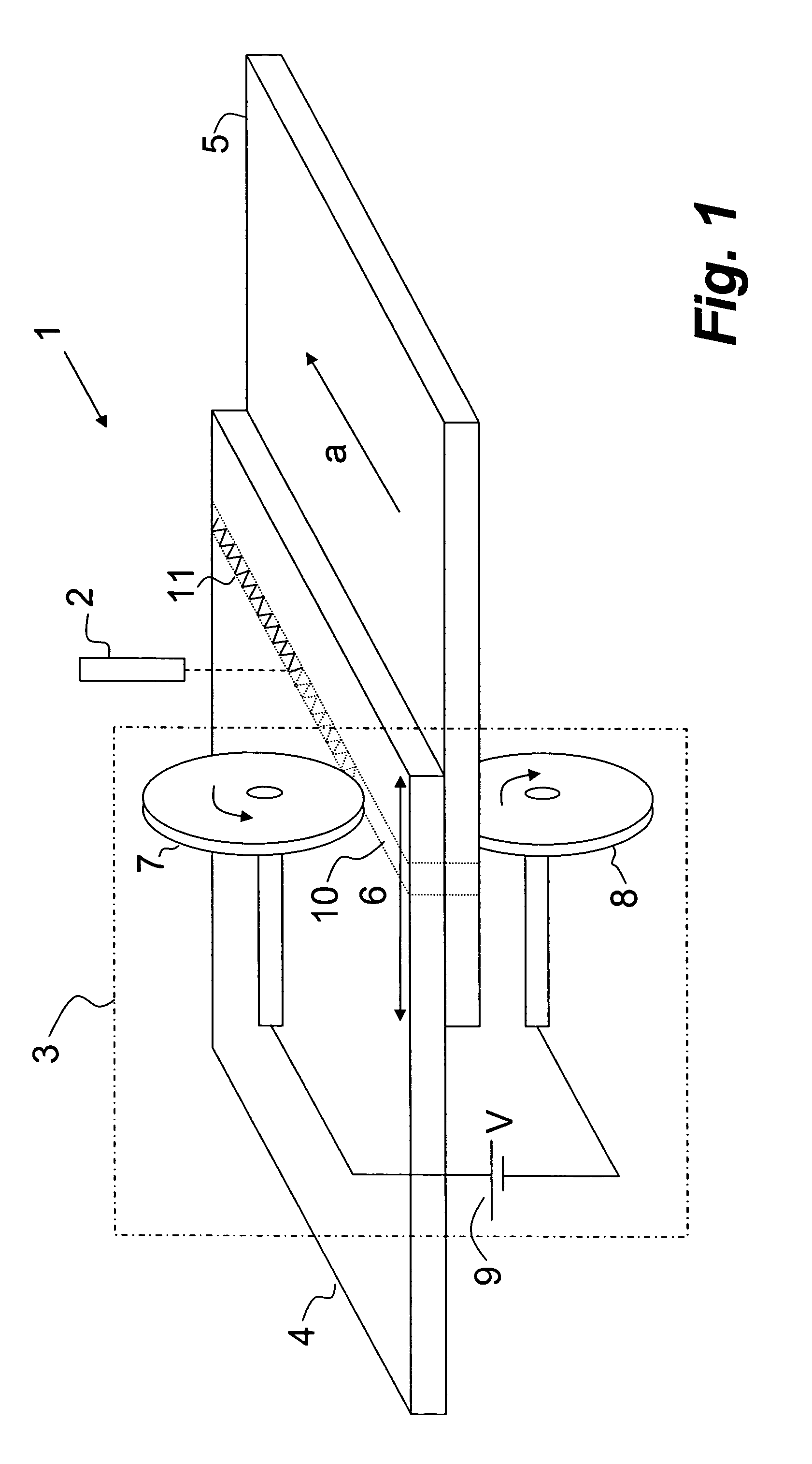
[0024] A first preferred embodiment of this invention will hereinafter be described with reference to FIG. 1. As disclosed in FIG. 1, a welding assembly 1 to be used for performing the inventive method, essentially comprises a resistance seam welding unit 3 and a laser welding unit 2, which may be integrated into a single welding unit, if desired.

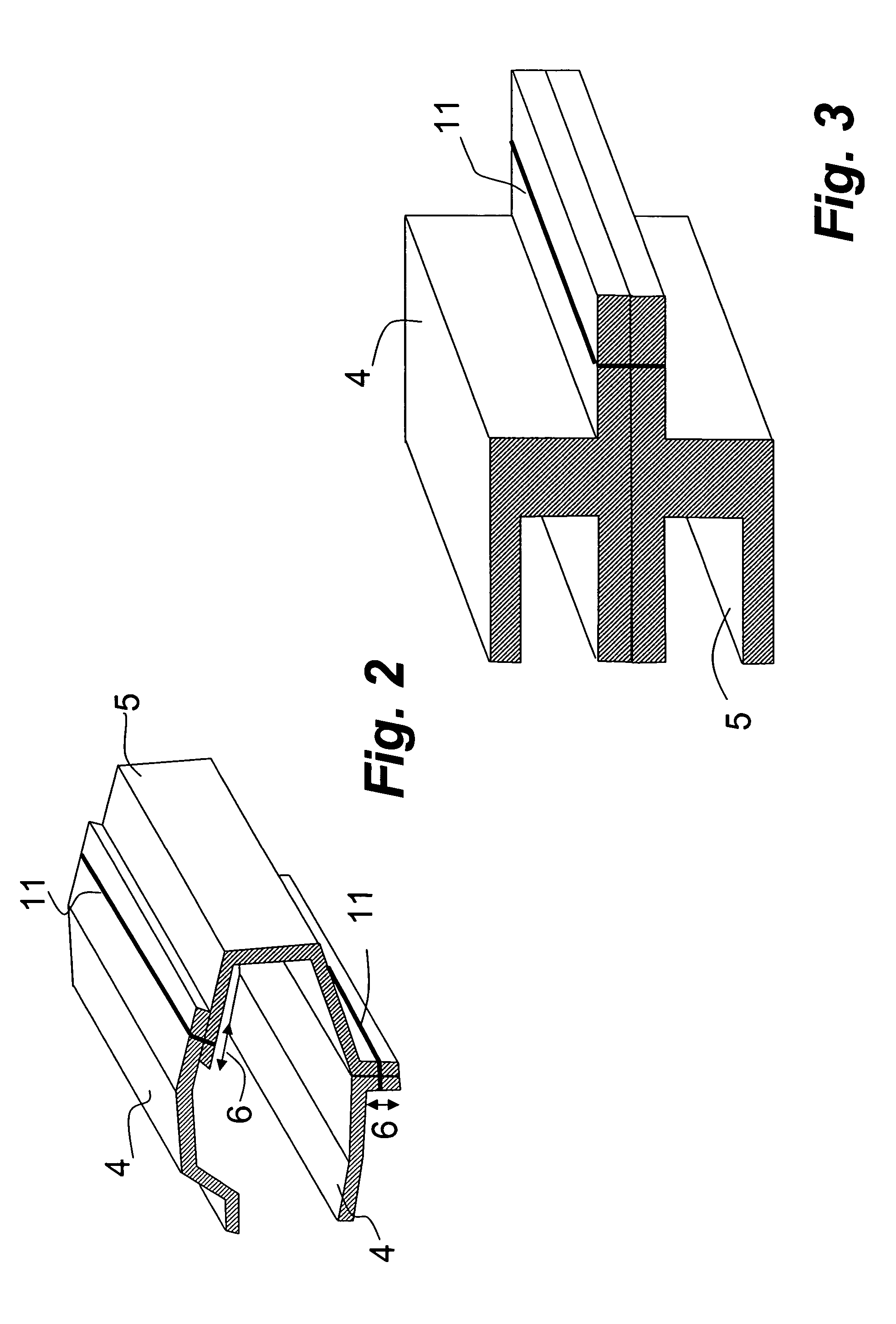
[0025] The welding assembly 1 is generally to be used to interconnect at least a first and a second body part 4, 5, each body part being formed of an electrically conducting material, such as a steel sheet material, for instance DP600 steel, mild steel, DP steel or Boron alloy steel. The steel sheet material may be stamped, extruded or casted. The first and second body part 4, 5 may be made of the same material or by different materials. An example of a typical material to be welded with the present method is a coated or uncoated steel sheet material having a thickness of about 0.5-3.0 mm. The resistance seam welding unit 3 is first arrang...


PUM

PropertyMeasurementUnit
poweraaaaaaaaaa
resistanceaaaaaaaaaa
widthaaaaaaaaaa

Abstract

This invention relates to a manufacturing method for interconnecting at least a first and a second body part of a sheet material to form a part of a vehicle body. The method comprising the steps of arranging the first and second body parts so that they essentially overlap and abut each other in an overlapping area, and exposing a welding zone of the overlapping area to a hybrid welding process in order to interconnect said first and second body parts in said overlapping area. The hybrid welding process comprises at least a first resistance seam welding step and a subsequent laser welding step. An apparatus for performing this manufacturing method is also disclosed.

Description

TECHNICAL FIELD OF THE INVENTION [0001] This invention relates to a manufacturing method for interconnecting at least a first and a second body part of a sheet material to form a part of a vehicle body. DESCRIPTION OF BACKGROUND ART [0002] Within the vehicle industry, different welding methods are today commonly used to join vehicle body parts with each other. [0003] One method that has increased in popularity during the last years is laser welding, in which a beam of laser radiation is used to perform a weld. Many different kinds of laser welding are available today. [0004] However, laser welding is often associated with a plurality of issues that need to be considered. One issue is that the surface conditions of the material to be welded are critical, and zinc coatings and oxide layers on the material to be welded may cause quality problems in the welded connection, in terms of porosity, undercut or even irregular weld geometry. The problems experienced when using laser welding ma...

Claims


Application Information

Patent Timeline
Patent Type & Authority Applications(United States)
IPC IPC(8): B23K26/26B23K11/06B23K26/24B23K26/32B23K26/42B23K28/02
CPCB23K11/061B23K26/246B23K26/3206B23K2201/185B23K26/421B23K28/02B23K26/3293B23K26/32B23K26/244B23K26/60B23K2101/185B23K2101/35B23K2103/08B23K2103/50
Inventor LARSSON, GERTLARSSON, LARS-OLA
Owner VOLVO CAR CORP
Why Eureka
Try Eureka