Hydrodynamic bearing device, and spindle motor and magnetic disk device using the same

a technology of hydrodynamic bearings and magnetic disks, which is applied in the direction of sliding contact bearings, mechanical instruments, mechanical instruments, etc., can solve the problems of inability to maintain the quantity of lubricant required for stabilizing the rotation of the bearing device, the device is insufficient reliability, and the amount of evaporation is significan

Inactive Publication Date: 2006-03-02
PANASONIC CORP
View PDF3 Cites 3 Cited by
  • Summary
  • Abstract
  • Description
  • Claims
  • Application Information

AI Technical Summary

Benefits of technology

[0015] and wherein R1 represents a C16 or higher alkyl group having at least one side-chain, R2 represents a C4 or higher alkyl group, the carbon number of R1 is greater than the carbon number of R2, R3 and R4 represent C8 or higher alkyl groups, A represents a C5 or higher CnH2n group, and at least one of R3, R4, and A have a branched structure.

Problems solved by technology

However, while it is possible to reduce the torque in such conventional hydrodynamic bearing devices, since the heat resistance of the lubricant is low (vapor pressure is high), the amount of evaporation will be significant when used over a long period, and it will not be possible to maintain the quantity of lubricant required for stabilized rotation of the bearing device.
Consequently, there will be problems with the device having inadequate reliability and the operational lifetime will be shorter.
However, this approach will entail problems in that this additional amount can increase the torque and bring a higher cost, and accommodating the additional space will make miniaturization more difficult.
Moreover, resins can undergo dissolution or swelling from coming into contact with ester-type lubricants, leading to the deterioration and lower performance of the resins used in the bearing components or in the material of the seals.
This limits the choice of resins that can be used.
Moreover, Japanese published unexamined application No. 2002-348586 teaches that when polymeric viscosity index improvers are added to the lubricant, the molecular bonds of the polymer are cleaved by shearing forces after long-term use at high speed rotations, which will cause marked changes in the viscosity, and raises concerns that the reliability of the hydrodynamic bearing will be impaired.

Method used


Image

  • Hydrodynamic bearing device, and spindle motor and magnetic disk device using the same
  • Hydrodynamic bearing device, and spindle motor and magnetic disk device using the same
  • Hydrodynamic bearing device, and spindle motor and magnetic disk device using the same

Examples


embodiment 1

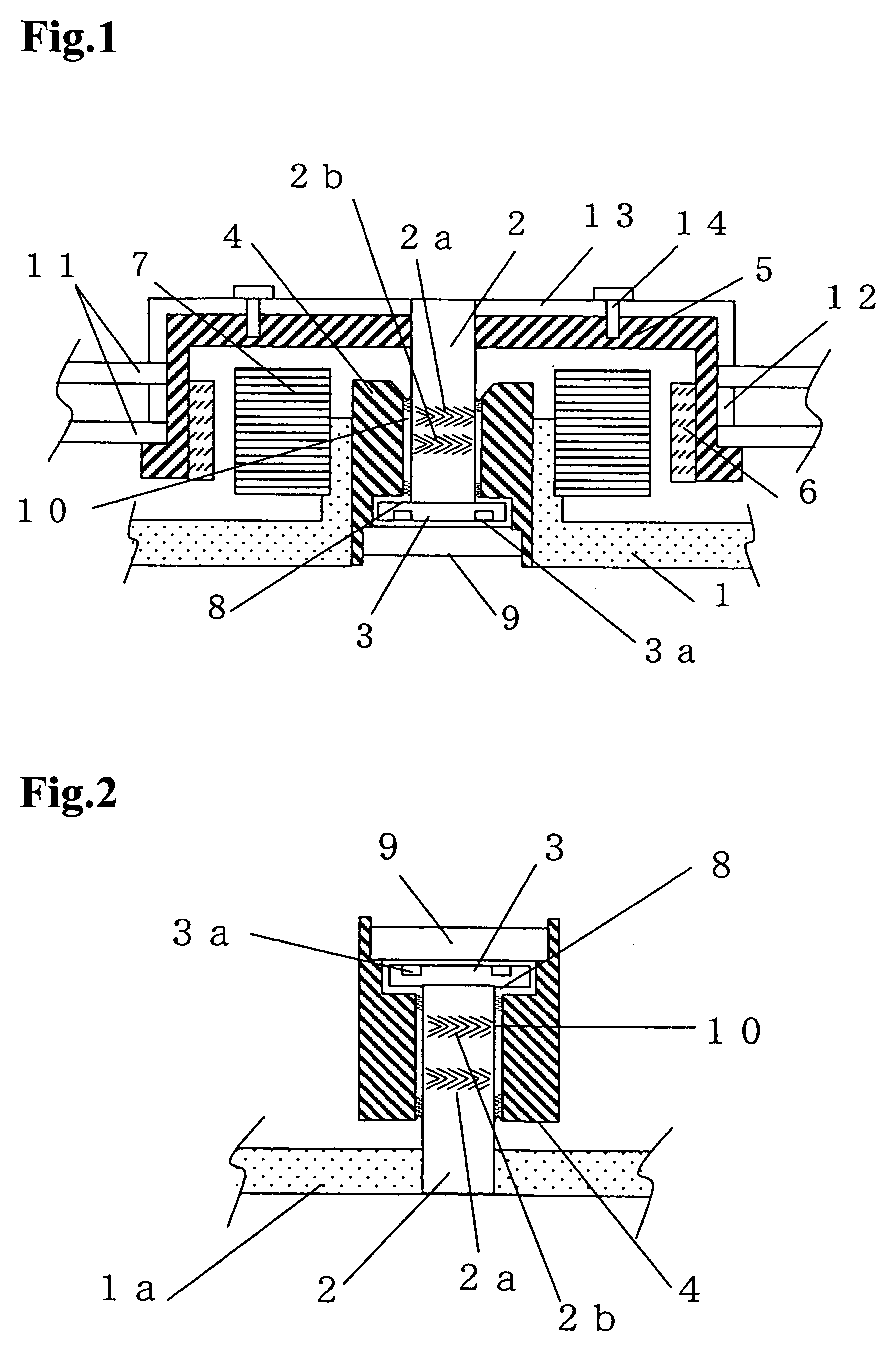
[0023] Embodiment 1 of the present invention is described with reference to FIG. 2. FIG. 2 is a cross section drawing of the main component for a hydrodynamic bearing device in a fixed shaft type of Embodiment 1.

[0024] In FIG. 2, radial dynamic pressure-generating grooves 2a and 2b are formed in a herringbone pattern on the outer circumferential surface of shaft 2. One end of the shaft 2 is affixed to thrust flange 3, and the other end is press fitted into base 1a. Shaft 2 and thrust flange 3 form the shaft component. The shaft component and the base 1a constitute the fixed component.

[0025] At the same time, sleeve 4 possesses a bearing bore that supports the shaft component. Thrust plate 9 is mounted on one end of sleeve 4. The shaft component is inserted into the bearing bore of sleeve 4 in such a manner as to face thrust plate 9 and thrust flange 3. Sleeve 4 and thrust plate 9 constitute the rotator. Thrust dynamic pressure-generating groove 3a is formed in a spiral pattern on ...

embodiment 2

[0064] Embodiment 2 of the present invention is explained by using FIG. 1. FIG. 1 is a cross section drawing of the main component of a magnetic disk device equipped with a spindle motor that possesses a rotating shaft-type hydrodynamic bearing device of Embodiment 2. The hydrodynamic bearing device in this Embodiment differs from the hydrodynamic bearing device in Embodiment 1 in FIG. 2 in the point that the present Embodiment has a rotating shaft type while Embodiment 1 has a fixed shaft type. With the exception of this point, Embodiment 2 is identical to Embodiment 1, and any of the elements having identical symbols have been omitted from the explanation.

[0065] In FIG. 1, radial dynamic pressure-generating grooves 2a and 2b are formed in a herringbone pattern on the outer circumferential surface of shaft 2, and the one end of shaft is affixed to thrust flange 3, and the other end is press fitted into hub 5. Shaft 2 and thrust flange 3 form the shaft component. In hub 5, two magn...

working examples 1 through 7

, COMPARATIVE EXAMPLES 1 THROUGH 3

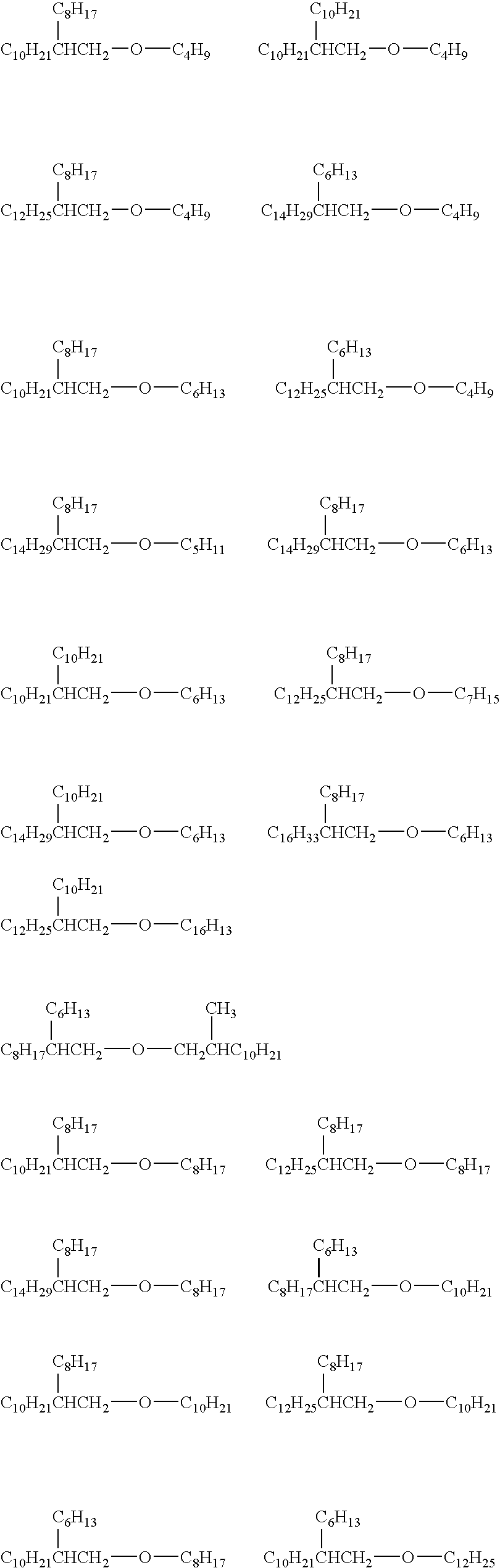
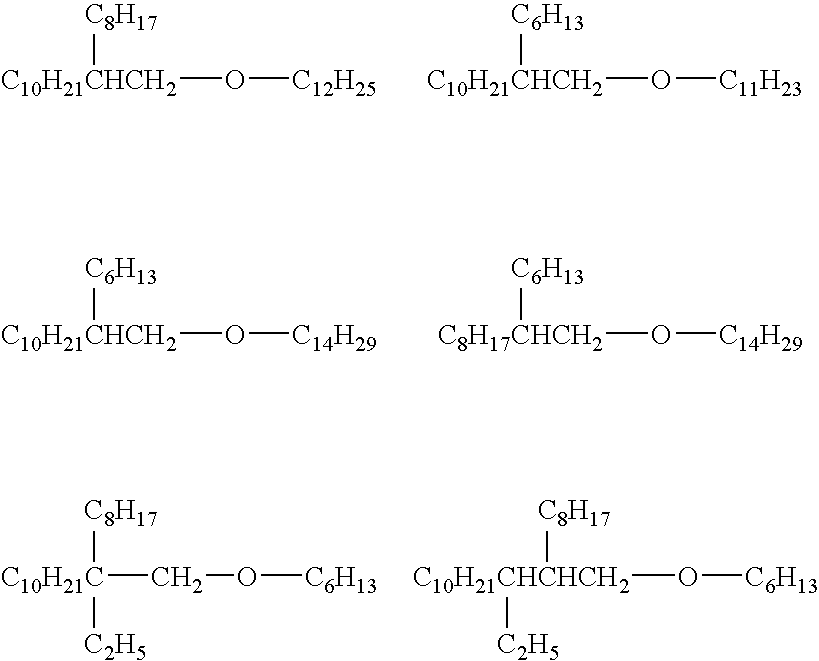
[0072] The lubricants were obtained by combining 0.5 wt % of n-octadecyl-3-(3,5-di-tert-butyl-4-hydroxyphenyl)propionate as the antioxidant with the base oils shown in Table 1.

[0073] The base oil of Working Example 1 is butyl isoeicosyl ether, for Working Example 2 is hexyl-2-octyldodecyl ether, for Working Example 3 is 1,3-bis-(decoxy)-2,2-dimethylpropane, for Working Example 4 is 1,5-bis-(octoxy)-3,3-diethylpentane, for Working Example 5 is 1,6-bis-(3,7-dimethyloctoxy)hexane, for Working Example 6 is a mixture of the three components 1,5-bis-(octoxy / nonoxy)-3,3-diethylpentane, and for Working Example 7 is 1-nonoxy-5-octoxy-3,3-diethylpentane.

[0074] For the Comparative Examples, except for the conventional base oils shown in Table 1 as lubricants, the lubricants were obtained in the same manner as for the Working Examples. The lubricant of Comparative Example 1 is dioctyl sebacate (DOS), the lubricant of Comparative Example 2 is the polyol ester ...


PUM

PropertyMeasurementUnit
temperature solidification pointaaaaaaaaaa
viscosityaaaaaaaaaa

Abstract

The invention provides a hydrodynamic bearing device, comprising at least one of a shaft and a sleeve having a dynamic pressure-generating mechanism, and a lubricant present in a gap between the shaft and the sleeve; wherein the lubricant contains at least one compound selected from the group consisting of aliphatic ethers having a total carbon number of 24 to 32 as represented in Formula (1) or Formula (2)
R1—O—R2  (1)
R3—O-A-O—R4  (2)
and wherein R1 represents a C16 or higher alkyl group having at least one side-chain, R2 represents a C4 or higher alkyl group, the carbon number of R1 is greater than the carbon number of R2, R3 and R4 represent C8 or higher alkyl groups, A represents a C5 or higher CnH2n group, and at least one of R3, R4, and A have a branched structure.

Description

BACKGROUND OF THE INVENTION [0001] 1. Field of the Invention [0002] The present invention relates to a dynamic pressure-type hydrodynamic bearing device, as well as a spindle motor and magnetic disk device using the same. [0003] 2. Description of the Prior Art [0004] A hydrodynamic bearing device comprises a shaft and a sleeve that supports the shaft, and a lubricant that is interposed in the gap between the two parts. With rotation of the shaft, the lubricant is gathered up by dynamic pressure-generating grooves that are formed on the shaft or sleeve, and generates pressure such that the shaft is supported within the sleeve without coming into contact therewith. As a result, when high-speed rotation is attained, ambient noise during the rotation can be alleviated. [0005] A spindle motor equipped with such a hydrodynamic bearing device can provide the requisite rotational accuracy with an increased recording density of the medium, and can furthermore provide excellent shock resistan...

Claims


Application Information

Patent Timeline
Patent Type & Authority Applications(United States)
IPC IPC(8): F16C32/06C10M129/16
CPCC10M105/18C10M2207/0406F16C33/109F16C17/107C10N2240/204C10N2040/18F16C2370/12
Inventor HIRATA, KATSUSHIOHNO, HIDEAKISHIRAISHI, TAKANORI
Owner PANASONIC CORP
Why Eureka
Try Eureka