Resin composite metal foil, laminate and process for the production of printed wiring board using the laminate

Active Publication Date: 2006-03-16
MITSUBISHI GAS CHEM CO INC
View PDF8 Cites 47 Cited by
  • Summary
  • Abstract
  • Description
  • Claims
  • Application Information

AI Technical Summary

Benefits of technology

[0011] According to the resin composite metal foil of the present invention, a metal foil having a metal foil surface with extremely small roughness can be used and there is provided a metal-foil-clad laminate which is excellent in the adhesive strength to a resin composition of a copper-clad laminate. Further, the use of the above resin composite metal foil can provide a metal-foil-clad laminate which is excellent in heat resistance and heat resistance after moisture absorption. The above metal-foil-clad laminate is suitably used as a high-density printed wiring board having a fine circuit. Therefore, the resin composite metal foil of the present invention has remarkably high industrial practi

Problems solved by technology

For this reason, there is a problem that, when a fine circuit is formed, part of convex portions is apt to remain on a resin surface of a laminate under the influence of the roughness of the mat surface of the metal foil.
When an etching time is extended for removing the convex portions completely, the circuit is over-etched and the location accuracy of the circuit and adhesive strength decrease.
However, the above metal foil is originally weak in adhesive strength.
When this metal foil is applied to a metal-clad laminate using a high heat resistant thermosetting resin, etc., a problem concerning fine circuits is that adhesive strength is insufficient.

Method used


Image

  • Resin composite metal foil, laminate and process for the production of printed wiring board using the laminate
  • Resin composite metal foil, laminate and process for the production of printed wiring board using the laminate
  • Resin composite metal foil, laminate and process for the production of printed wiring board using the laminate

Examples


example 1

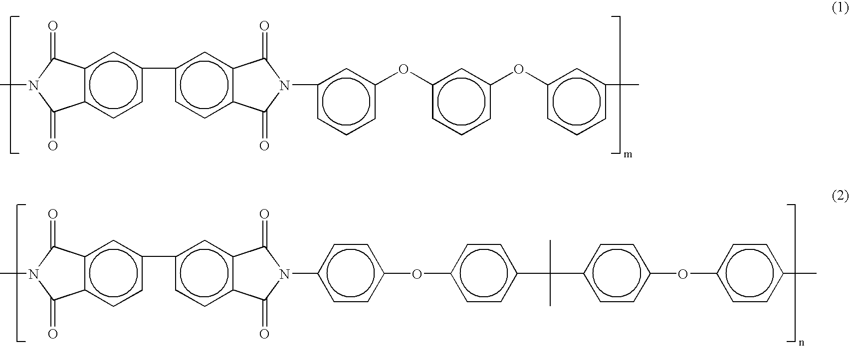
[0039] A 2-liter three-necked flask having an anchor type stirring rod made of stainless steel, a trap equipped with a nitrogen-introducing tube and a stopcock, and a reflux condenser having a cooling tube with a ball, installed on the trap, was charged with 117.68 g (400 mmol) of 3,4,3′,4′-biphenyltetracarboxylic dianhydride, 87.7 g (300 mmol) of 1,3-bis(3-aminophenoxy)benzene, 4.0 g (40 mmol) of γ-valerolactone, 4.8 g (60 mmol) of pyridine, 300 g of N-methyl-2-pyrrolidone (to be referred to as “NMP” hereinafter) and 20 g of toluene. The mixture was heated at 180° C. for 1 hour and then cooled down to about room temperature. 29.42 g (100 mmol) of 3,4,3′,4′-biphenyltetracarboxylic dianhydride, 82.12 g (200 mmol) of 2,2-bis{4-(4-aminophenoxy)phenyl}propane, 200 g of NMP and 40 g of toluene were added and the components were mixed at room temperature for 1 hour and then heated at 180° C. for 3 hours, to obtain a block copolymer polyimide resin solution having a solid content of 38%. T...

example 2

[0041] A copper-clad laminate having a thickness of 0.4 mm was produced in the same manner as in Example 1 except that the F0-WS foil as an electrolytic copper foil used in Example 1 was replaced with F3-WS foil (Rz=2.4 μm, supplied by Furukawa circuit foil Co., Ltd.) having a thickness of 12 μm. Table 1 shows the evaluation results.

example 3

[0042] A 2-liter three-necked flask having an anchor type stirring rod made of stainless steel, a trap equipped with a nitrogen-introducing tube and a stopcock, and a reflux condenser having a cooling tube with a ball, installed on the trap, was charged with 117.68 g (400 mmol) of 3,4,3′,4′-biphenyltetracarboxylic dianhydride, 123.18 g (300 mmol) of 2,2-bis{4-(4-aminophenoxy)phenyl}propane, 4.0 g (40 mmol) of γ-valerolactone, 4.8 g (60 mmol) of pyridine, 300 g of NMP and 20 g of toluene. The mixture was heated at 180° C. for 1 hour and then cooled down to about room temperature. Then, 29.42 g (100 mmol) of 3,4,3′,4′-biphenyltetracarboxylic dianhydride, 58.47 g (200 mmol) of 1,3-bis(3-aminophenoxy)benzene, 200g of NMP and 40 g of toluene were added and the components were mixed at room temperature for 1 hour and then heated at 180° C. for 3 hours, to obtain a block copolymer polyimide resin solution having a solid content of 38%. The block copolymer polyimide resin had a formula (1):...


PUM

PropertyMeasurementUnit
Temperatureaaaaaaaaaa
Timeaaaaaaaaaa
Thicknessaaaaaaaaaa

Abstract

A resin composite metal foil comprising a metal foil and a layer of a block copolymer polyimide resin formed on one surface of the metal foil, a metal-foil-clad laminate using the above resin composite metal foil, a printed wiring board using the above metal-foil-clad laminate, and a process for the production of a printed wiring board comprising removing an external layer metal foil of a metal-foil-clad laminate and forming a conductor layer on an external layer insulating layer by plating, wherein the metal-foil-clad laminate comprises a layer of a block copolymer polyimide resin which layer is in contact with the external layer metal foil.

Description

FIELD OF THE INVENTION [0001] The present invention relates to a resin composite metal foil for use in a printed wiring board, a metal-foil-clad laminate and a printed wiring board each of which uses the resin composite metal foil, and a process for the production of a printed wiring board whose external layer conductor layer is formed by plating. [0002] A metal foil having a metal foil surface with extremely small roughness can be used for the resin composite metal foil obtained by the present invention. The resin composite metal foil has an excellent adhesive strength to a resin composition. The metal-foil-clad laminate obtained therefrom has excellent heat resistance and is suitably used for a high-density printed wiring board having a fine circuit. [0003] A printed wiring board obtained by the process for the production of a printed wiring board provided by the present invention is excellent in the adhesive strength between an external layer conductor layer and an external layer...

Claims


Application Information

Patent Timeline
IPC IPC(8): H01B13/00
CPCB32B15/08B32B15/20B32B27/281B32B2250/02B32B2307/202B32B2307/75Y10S428/901C08G73/10C08G73/1042C08G73/105C08G73/1078H05K1/0346H05K2203/1152B32B2457/08Y10T428/31721
Inventor OMORI, TAKABUMINOZAKI, MITSURUNAGATA, EIJIYANO, MASASHI
Owner MITSUBISHI GAS CHEM CO INC
Why Eureka
Try Eureka