Relay telescope for high power laser alignment system

a laser alignment and laser technology, applied in the field of high-power laser systems and mirror systems for high-power lasers, can solve the problems of affecting the production throughput of lasers with both sufficient energy and sufficient repetition rate, affecting the production throughput of lasers at affordable costs, and unable to provide sufficient intense or deep treatment of shot peening, etc., to achieve the effect of avoiding damage to the baffle and reducing the fluence level of the impact area of the blocked beam

Active Publication Date: 2006-03-23
LAWRENCE LIVERMORE NAT SECURITY LLC
View PDF55 Cites 20 Cited by
  • Summary
  • Abstract
  • Description
  • Claims
  • Application Information

AI Technical Summary

Benefits of technology

[0021] In some embodiments of the present invention, the laser system includes an optical path having an intracavity relay telescope with a telescope focal point for imaging an output of the gain medium between an image location at or near the gain medium and an image location at or near an output coupler for the laser system. The intracavity relay telescope includes a first relay lens and a second relay lens then arranged to focus the beam at a telescope focal point within a vacuum chamber. A kinematic mount is provided within a vacuum chamber, and adapted to secure beam baffles near the telescope focal point. An access port on the vacuum chamber is adapted for allowing insertion and removal of the beam baffles. A first baffle formed using an alignment pinhole aperture is used during alignment of the laser system. A second tapered baffle replaces the alignment aperture during operation and acts as a far-field baffle. The tapered baffle comprises a solid member having an optically transparent channel, such as a hollow bored through the member. The optically transparent channel has openings on opposite ends of the solid member and a waist within the solid member near the telescope focal point. The waist is smaller than the openings on the ends. The channel has sides which taper near the waist so that off angle beams strike the baffle at a grazing angle of incidence. By striking the baffle at a grazing angle of incidence, the fluence levels at the impact areas of the blocked beams are reduced, and damage to the baffle is avoided. In some embodiments, near field baffles are also mounted on the relay telescope adjacent to at least one of the first and second relay lenses.

Problems solved by technology

However, for many applications, shot peening does not provide sufficiently intense or deep treatment or cannot be used because of its detrimental effect on the surface finish.
However, lasers with both sufficient energy and sufficient repetition rate to achieve production throughput at affordable costs have been difficult to provide.
The non-separated portion of the beam continues passing through the relay telescope and is re-amplified, often obtaining sufficient power so that it can become a damage problem elsewhere in the optical system.
This is critical since an SBS phase conjugator very effectively reverses the optical wavefront of the input beam but often does not reproduce the irradiance profile with high fidelity.
Therefore, wavefront errors that are converted to irradiance distribution errors may not be adequately corrected.
However, the multi-pass amplifier system can generate undesirable weak “ghost” beams that result from small shortcomings in the polarization control used for beam path switching.
Such beams can then cause damage to optical components in the system as they propagate within the amplifier.
An important issue in the operation of a high pulse energy, high average power, solid-state laser is preventing the possibility of internal optical damage to the amplifier due to nonlinear self-focusing of the amplified beam in the SBS medium.
Since this variation in index is correlated to small irradiance variations in the beam, these irradiance variations can grow until the beam profile breaks up into very small and very intense filaments, which damage the gain medium.
This process is referred to as nonlinear self-focusing and can pose a serious limitation to the maximum pulse energy and peak power available from a solid-state laser.
In the high power, short pulse length, laser systems needed for these applications, controlling pulse duration is difficult.
This reflected light can damage the laser optics if allowed to propagate sufficiently far back up the axis.
This can cause the reflected beam to come to focus at undesirable locations in the optical beam train such as at the surfaces of critical optical components such as lenses and mirrors.
This can result in permanent damage to these critical components in the optical beam train.
Further, the local shape and curvature of the target can add to the focusing characteristics of the reflected beam, resulting in unexpected focused hot spots in the reflected beam.
Small ripples and non-uniformities in the surface of the water can also result in beam distortion in the reflected beam and unexpected focusing characteristics.

Method used


Image

  • Relay telescope for high power laser alignment system
  • Relay telescope for high power laser alignment system
  • Relay telescope for high power laser alignment system

Examples


Embodiment Construction

[0036] A detailed description of embodiments of the present invention is provided with reference to FIGS. 1-10.

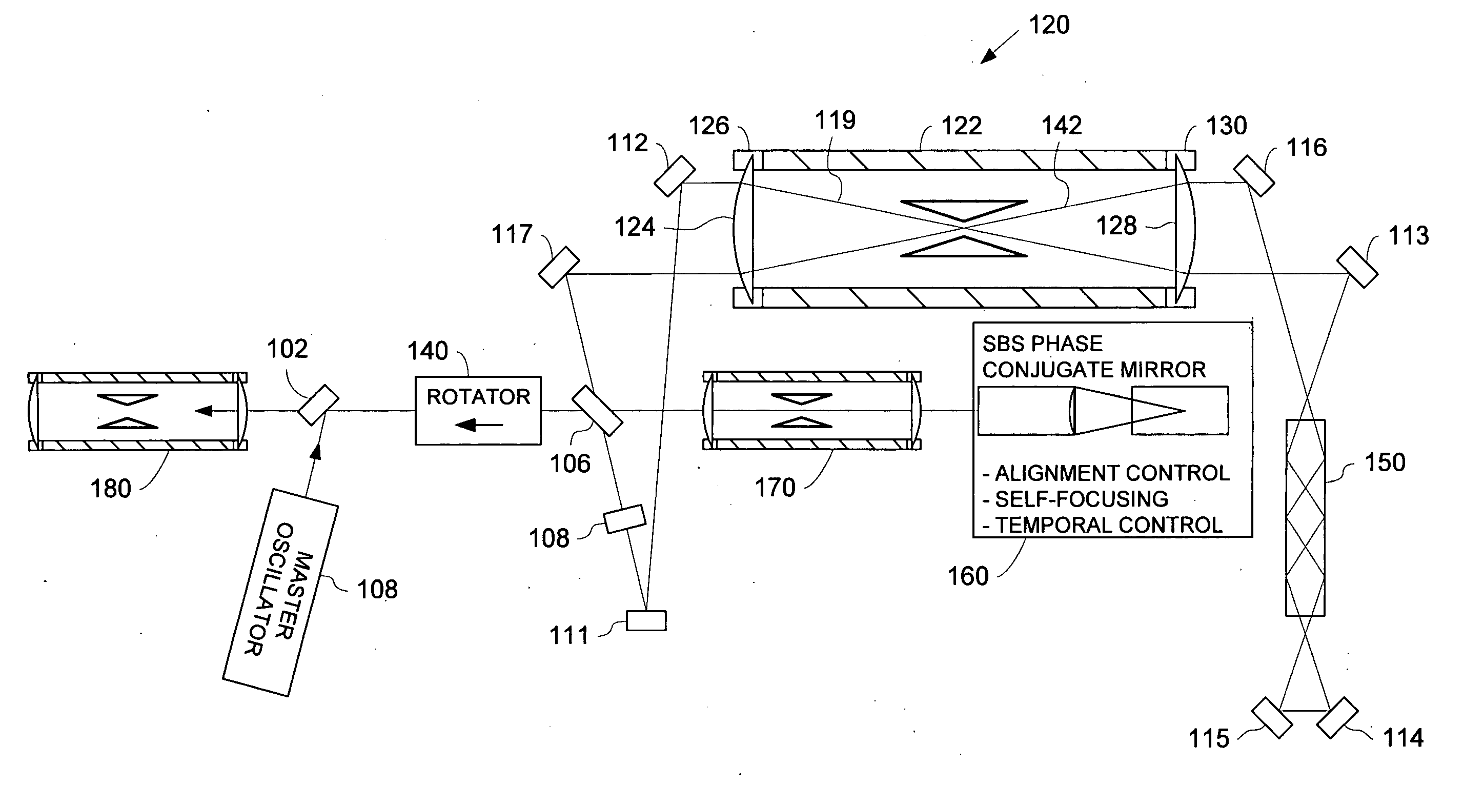
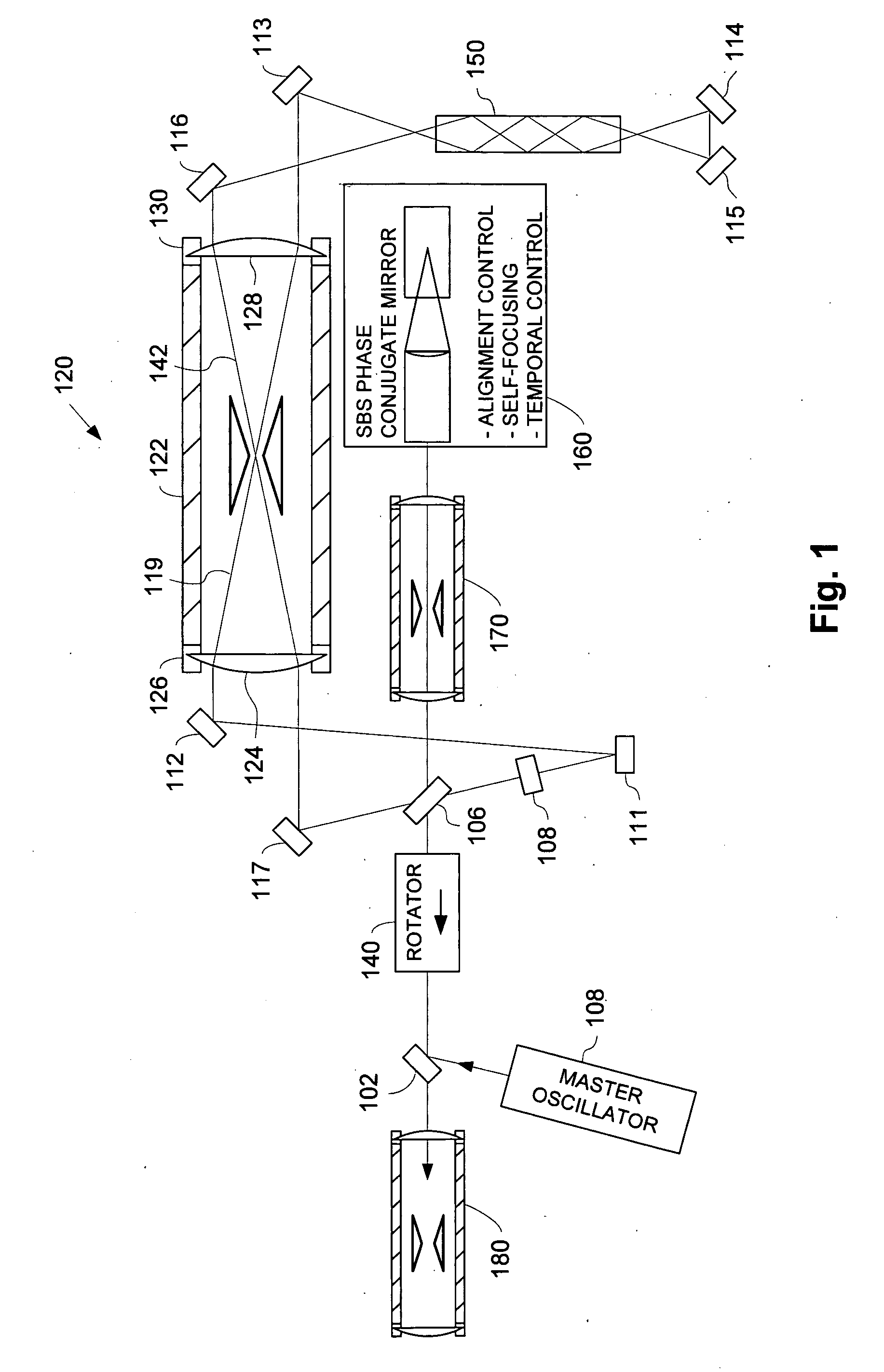
[0037] The basic architecture of the master oscillator / power amplifier configuration with a regenerative laser amplifier including an SBS phase conjugator mirror system and relay telescope with a baffle is shown in FIG. 1. The embodiment of FIG. 1 is an improved version of a similar amplifier described in U.S. Pat. No. 5,239,408, which is incorporated by reference as if fully set forth herein. The amplifier system of FIG. 1 includes a rotator 140, such as a Pockels cell or Faraday rotator, a first intra-cavity relay telescope 120, a slab-shaped gain medium 150, a second intra-cavity relay telescope 170 and an SBS phase conjugator / mirror system 160. The slab 150 is enclosed in a pump cavity (not shown). Two polarizers 102 and 106 are also included for capturing an input pulse, and extracting an output pulse, respectively. Seven flat, highly reflecting mirrors 111, 112, 113,...


PUM

PropertyMeasurementUnit
grazing angleaaaaaaaaaa
pore sizeaaaaaaaaaa
focal lengthaaaaaaaaaa

Abstract

A laser system includes an optical path having an intracavity relay telescope with a telescope focal point for imaging an output of the gain medium between an image location at or near the gain medium and an image location at or near an output coupler for the laser system. A kinematic mount is provided within a vacuum chamber, and adapted to secure beam baffles near the telescope focal point. An access port on the vacuum chamber is adapted for allowing insertion and removal of the beam baffles. A first baffle formed using an alignment pinhole aperture is used during alignment of the laser system. A second tapered baffle replaces the alignment aperture during operation and acts as a far-field baffle in which off angle beams strike the baffle a grazing angle of incidence, reducing fluence levels at the impact areas.

Description

REFERENCE TO RELATED APPLICATION [0001] The present application is a division of U.S. patent application Ser. No. 10 / 766,224, filed 28 Jan. 2004 entitled LASER AMPLIFIER SYSTEM INCLUDING A RELAY TELESECOPE (as amended), which claims the benefit of U.S. Provisional Patent Application No. 60 / 515,727, entitled RELAY TELESCOPE, HIGH POWER LASER ALIGNMENT SYSTEM, AND LASER PEENING METHOD AND SYSTEM USING SAME, invented by Dane et al., and filed on 30 Oct. 2003.GOVERNMENT CONTRACT INFORMATION [0002] The United States Government has rights in this invention pursuant to Contract No. W-7405-ENG-48 between the United States Department of Energy and the University of California for the operation of Lawrence Livermore National Laboratory.BACKGROUND OF THE INVENTION [0003] 1. Field of the Invention [0004] The present invention relates to methods using high power laser systems, and mirror systems for high power lasers based on Stimulated Brillouin Scattering SBS phase conjugation, to use of such ...

Claims


Application Information

Patent Timeline
Patent Type & Authority Applications(United States)
IPC IPC(8): H01S3/00H01S3/05H01S3/10H01S3/30
CPCB23K26/0069B23K26/032B23K26/0639B23K26/0648B23K26/0665C21D10/005H01S3/305G02B7/003H01S3/005H01S3/025H01S3/10076H01S3/2333G02B5/005B23K26/064B23K26/356
Inventor DANE, C. BRENTHACKEL, LLOYDHARRIS, FRITZ
Owner LAWRENCE LIVERMORE NAT SECURITY LLC
Why Eureka
Try Eureka