

Fuel cell system
a fuel cell and system technology, applied in the field of fuel cell systems, can solve the problems of deterioration of cell capability, deterioration of system cell performance, and deterioration of system cell capability, so as to prevent deterioration of cell performance, effectively reclaim, and suppress metal ions dissolution
- Summary
- Abstract
- Description
- Claims
- Application Information
AI Technical Summary
Benefits of technology
Problems solved by technology
Method used
Image

Examples
example
Examples 1 to 6, and Comparative Example 1
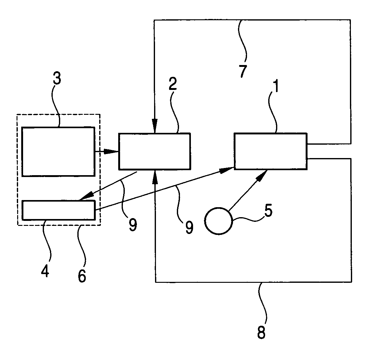
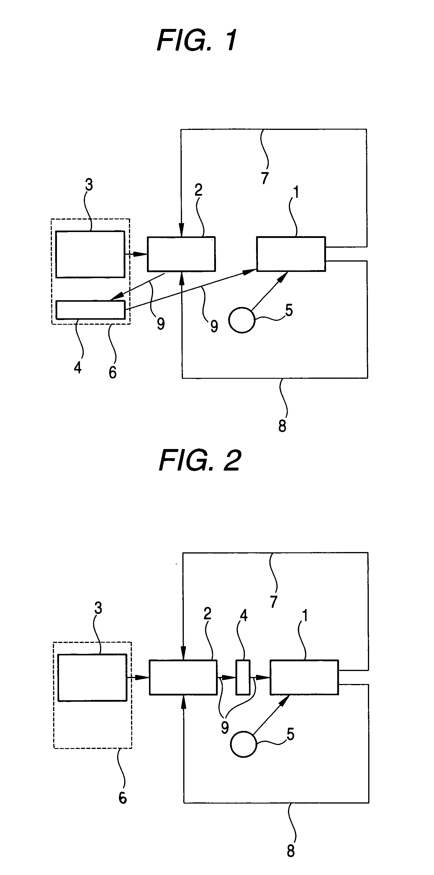
[0040] Into a beaker were placed 10 g of pulverized zirconium phosphate and about 50 ml of Nafion solution (20% non-volatile content dispersed in a solvent consisting of ethanol and propanol) which is provided with cation exchange capability. After the mixture was mixed for 1 hr by means of a stirrer, the piping used in an cell unit was immersed in the slurry whereby the ion exchange material was coated on the inner surface of the piping. (Example 1) After coating, the coated layer was dried at a temperature between room temperature and 100° C. The coating and drying operations were repeated until the coated layer has the pre-determined thickness (about 30 μm). Since the high polymer material (silicone, PEEK or PFA) usually used for piping is incorporated with various additives such as catalysts in the synthetic step, inorganic metal ions included in the additives dissolve out when the material is exposed to an organic solvent such as metha...
examples 7 to 12
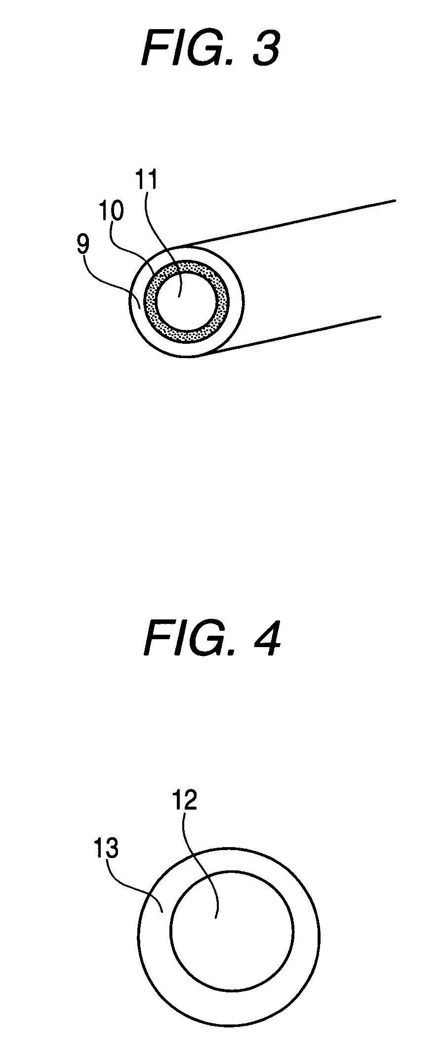
[0048] Into a beaker were placed 10 g of pulverized zirconium phosphate and about 25 ml of Nafion solution (20% non-volatile content dispersed in a solvent consisting of ethanol and propanol), which was provided with cation exchange capability. And after mixed for 1 hr by means of a stirrer, the mixture was charged into a mold to fabricate thin pieces with thicknesses of from 10 to 250 μm via drying at a temperature ranging from room temperature to 70° C. (Example 7) Then, about 8 g of particles with particle diameters from 400 to 600 μm (FIG. 4) obtained by braking and fractionating the thin pieces was charged together with the methanol in the fuel cartridge (about 150 ml, 100% methanol) and used as a fuel cartridge. Meanwhile, as shown in FIG. 4, the inorganic-organic composite ion exchange member is constituted of an interior part made of an inorganic ion exchange member 12 and an exterior part made of an organic member 13. The methanol in the fuel cartridge is kept in a polyethy...
examples 13 to 18
[0056] After 30 g of zirconium phosphate, 30 g of water and 20 g of tetramethoxysilane were mixed in a beaker, the resulting mixture was coated on a Teflon board to give a thin film of 100 to 200 μm thickness. After drying, this thin film was subjected to heat treatment at 70° C. (Example 13), 100° C. (Example 14), 150° C. (Example 15), 200° C. (Example 16), 250° C. (Example 17), or 300° C. (Example 18) for 3 hr. Then, each film piece was pulverized and fractionated to prepare an ion filter containing 5 g of 10 to 100 μm size particles. To confirm the ion exchange capability of each ion filter, the ion filter thus prepared was immersed for 10 min in 100 ml of 3% methanol aqueous solution which contained 1 ppm of aluminum ion prior to the immersion. And, the change in the aluminum ion concentration in the aqueous solution was investigated. The aluminum ion content in each example decreased. It was proved that the ion filters subjected to heat treatment at 100 to 250° C. have particul...
PUM
| Property | Measurement | Unit |
|---|---|---|
| Specific surface area | aaaaa | aaaaa |
| Particle size distribution | aaaaa | aaaaa |
| Fraction | aaaaa | aaaaa |
Abstract
Description
Claims
Application Information