Rechargeable battery and method for fabricating the same

a rechargeable battery and battery technology, applied in the field of rechargeable batteries, can solve the problems of increasing the time consumed for film lamination, limiting the thinning and miniaturization of the battery, and the difficulty of film lamination, so as to achieve excellent reversibility of absorption and release of lithium ions, prolong the cycle life of the battery, and excellent battery characteristics

Inactive Publication Date: 2006-04-06
KK TOSHIBA
View PDF6 Cites 30 Cited by
  • Summary
  • Abstract
  • Description
  • Claims
  • Application Information

AI Technical Summary

Benefits of technology

[0014] An important feature of the first and second rechargeable batteries and the first and second fabrication methods of the invention is that a conductive metal oxide is used for either the positive electrode or the negative electrode current collector while using a specifically chosen negative electrode active material. This conductive metal oxide hardly exhibits any appreciable change in quality due to heating—in particular, heat application in oxidizable atmospheres. Thus it is possible to fabrica

Problems solved by technology

Unfortunately, such prior known methodology having these steps is encountered with limits to battery thinning and miniaturization.
As the prior known solid electrolyte batteries are fabricated by thin-film fabrication processes, such as sputter techniques, these batteries suffer from problems as to an increase in time consumed for film fabrication, difficulty in film lamination, and an increase in production costs.
Another problem faced with the prior art solid elect

Method used


Image

  • Rechargeable battery and method for fabricating the same
  • Rechargeable battery and method for fabricating the same
  • Rechargeable battery and method for fabricating the same

Examples


example 1

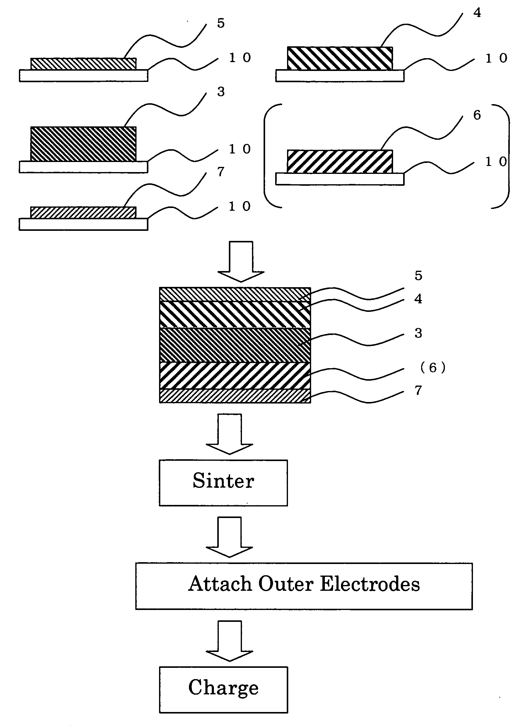
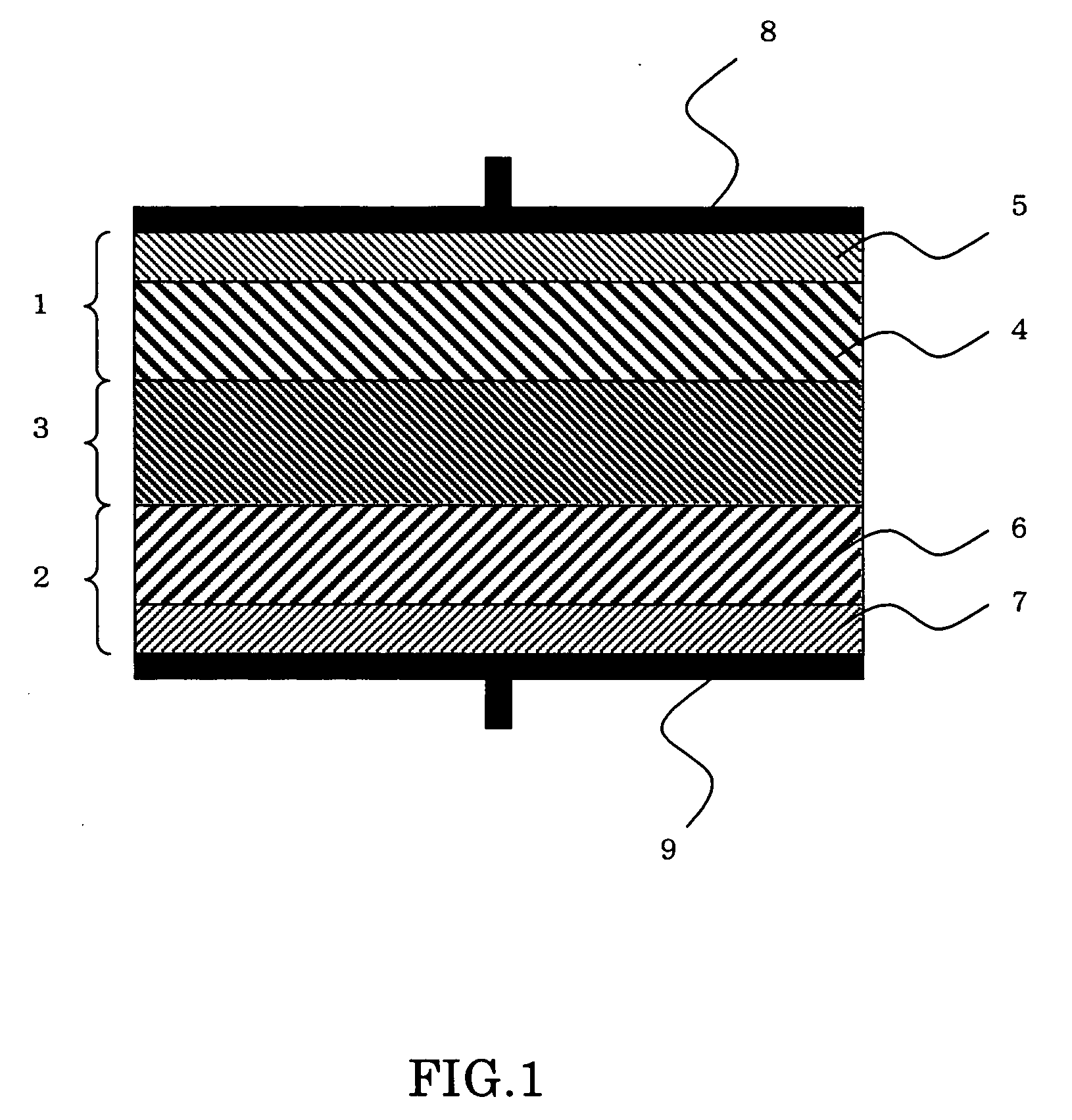
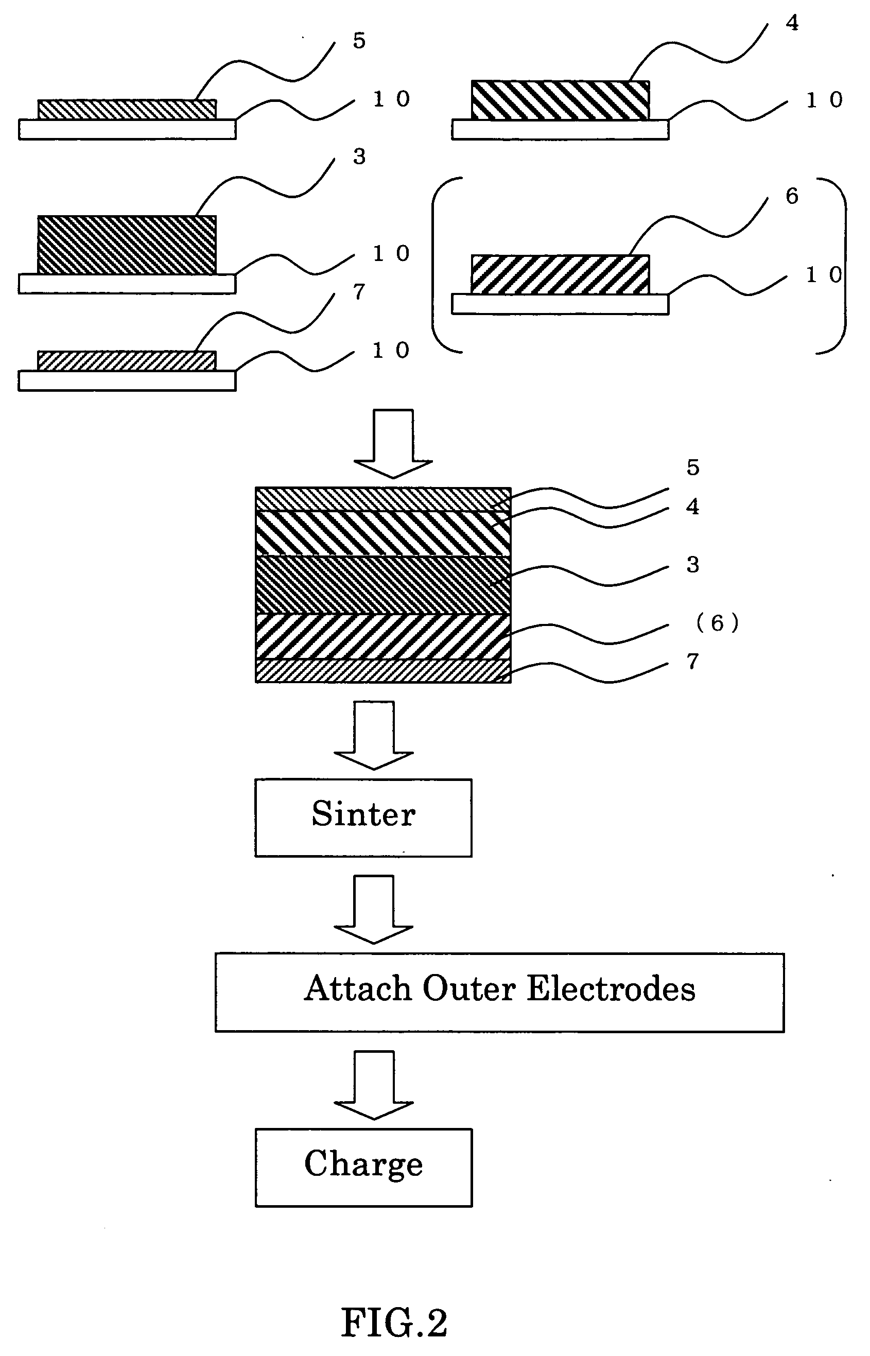
[0046] A rechargeable battery, also called secondary battery, was prepared by a method having the steps which follow. The battery has a unitary laminate structure such as shown in FIG. 1. Some major process steps in the manufacture of such battery are illustrated in cross-section in FIG. 2.

[0047] A slurry was prepared by admixture and blend of chosen inorganic solid electrolytic materials into N-methylpyrrolidone (NMP), which are 95 weight percent (wt %) of lantern lithium titanate (LixLayTiO3) powder and 5 wt % of polyvinyliden fluoride (PVdF). Then, deposit this slurry on a carrier sheet 10, followed by dehydration. This resulted in an inorganic solid electrolyte layer 3 being formed on the carrier sheet 10.

[0048] A slurry was prepared by mixture and blend of 95 wt % of antimony-doped tin oxide (SnO2) powder and 5 wt % of polyvinyliden fluoride (PVdF) into N-methylpyrrolidone (NMP). Deposit this slurry on carrier sheets 10, and then dry it, resulting in a positive current collec...

example 2

[0053] A battery was formed, which is similar to that of Example 1 except that its positive and negative current collector layers are made of an indium oxide (In2O3)

[0054] The battery completed is then trimmed or diced vertically relative to its laminate faces. As a result of execution of SEM-EDX analysis and XRD analysis, there was affirmed the presence of a Li—In alloy layer for use as the negative active layer 6 between the negative collector sheet 7 and the inorganic solid electrolyte layer 3.

example 3

[0055] A battery was formed, which is similar to that of Example 1 except that its positive and negative collector layers are made of zinc oxide (ZnO).

[0056] The battery completed is then diced vertically relative to its laminate faces. Then, SEM-EDX analysis and XRD analysis were done to affirm the presence of a Li—Zn alloy layer for use as the negative active layer 6 between the negative collector sheet 7 and inorganic solid electrolyte layer 3.


PUM

PropertyMeasurementUnit
Electric potential / voltageaaaaaaaaaa
Electrical conductoraaaaaaaaaa

Abstract

An inorganic solid electrolytic rechargeable battery capable of offering excellent battery characteristics is disclosed. The battery has positive and negative electrodes and an inorganic electrolyte interposed therebetween. The positive and negative electrodes are each made up of an active material layer and a current collector layer. The positive electrode collector layer or the negative electrode collector layer is a conductive metal oxide layer. The negative electrode active material layer is made of lithium metals or lithium alloys. This negative active layer may alternatively be made of a material which causes an operation voltage potential of the negative electrode to become more noble than 1.0 V with respect to the potential of a metallic lithium. A complexity-reduced fabrication method of the rechargeable battery is also disclosed.

Description

CROSS-REFERENCE TO RELATED APPLICATION [0001] This application is based upon and claims the benefit of priority from the prior Japanese Patent Application No. 2004-289946, filed on Oct. 1, 2004, the entire contents of which are incorporated herein by reference.BACKGROUND OF THE INVENTION [0002] 1. Field of the Invention [0003] The present invention relates to a rechargeable battery using an inorganic solid electrolyte and a fabrication method thereof. [0004] 2. Related Art [0005] As the quest grows for downsizing and weight-saving of electronic equipment, electrochemical storage battery cells also are more strongly demanded to satisfy such small-size / light-weight requirements. To achieve a battery which fully meets these requirements, ultra-small and ultra-thin batteries are under consideration, which are evolved from the integration or “collaboration” of thin-film architectures and battery material technologies. These thickness-reduced or “slim” batteries are expected to be used as...

Claims


Application Information

Patent Timeline
IPC IPC(8): H01M4/66H01M4/04H01M4/02H01M4/131H01M4/134H01M4/1395H01M4/40H01M4/48H01M4/485H01M4/58H01M10/052H01M10/0562H01M10/058H01M10/0585
CPCH01M2/1673Y10T29/49108H01M4/485H01M4/581H01M4/5825H01M4/626H01M4/66H01M4/661H01M8/04291H01M10/0525H01M10/0562H01M10/0585Y02E60/122Y02E60/50H01M4/134Y02E60/10H01M50/46Y02P70/50
Inventor HARADA, KOICHIINAGAKI, HIROKISUENAGA, SEIICHI
Owner KK TOSHIBA
Why Eureka
Try Eureka