Structured composite dielectrics

a composite dielectric and film technology, applied in the field of structured composite dielectric films, can solve the problems of not knowing the structure or the dielectric constant of films, and achieve the effect of higher energy storage capacity

Inactive Publication Date: 2006-04-06
TPL SRL
View PDF78 Cites 31 Cited by
  • Summary
  • Abstract
  • Description
  • Claims
  • Application Information

AI Technical Summary

Benefits of technology

[0016] A primary advantage of the present invention is that it provides for higher energy storage capability.
[0017] Other objects, advantages and novel features, and further scope of applicability of the present invention are set forth in part in the detailed description to follow, taken in conjunction with the accompanying drawings, and in part will become apparent to those skilled in the art upon examination of the following, or may be learned by practice of the invention. The objects and advantages of the invention may be realized and attained by means of the instrumentalities and combinations particularly pointed out in the appended claims.
[0018] The accompanying drawings, which are incorporated into and form a part of the specification, illustrate one or more embodiments of the present invention and, together with the description, serve to explain the principles of the invention. The drawings are only for the purpose of illustrating one or more preferred embodiments of the invention and are not to be construed as limiting the invention. In the drawings:
[0019]FIG. 1 is a schematic for electrode configuration for producing particle alignment;
[0020]FIG. 2 is a diagram of film extrusion using slot die coating;
[0021]FIG. 3 is a diagram of an aligning fixture;

Problems solved by technology

However, structures comprising films or exhibiting higher dielectric constants are not known.

Method used


Image

  • Structured composite dielectrics
  • Structured composite dielectrics
  • Structured composite dielectrics

Examples


example

[0052] Optical Microscopy Evaluations

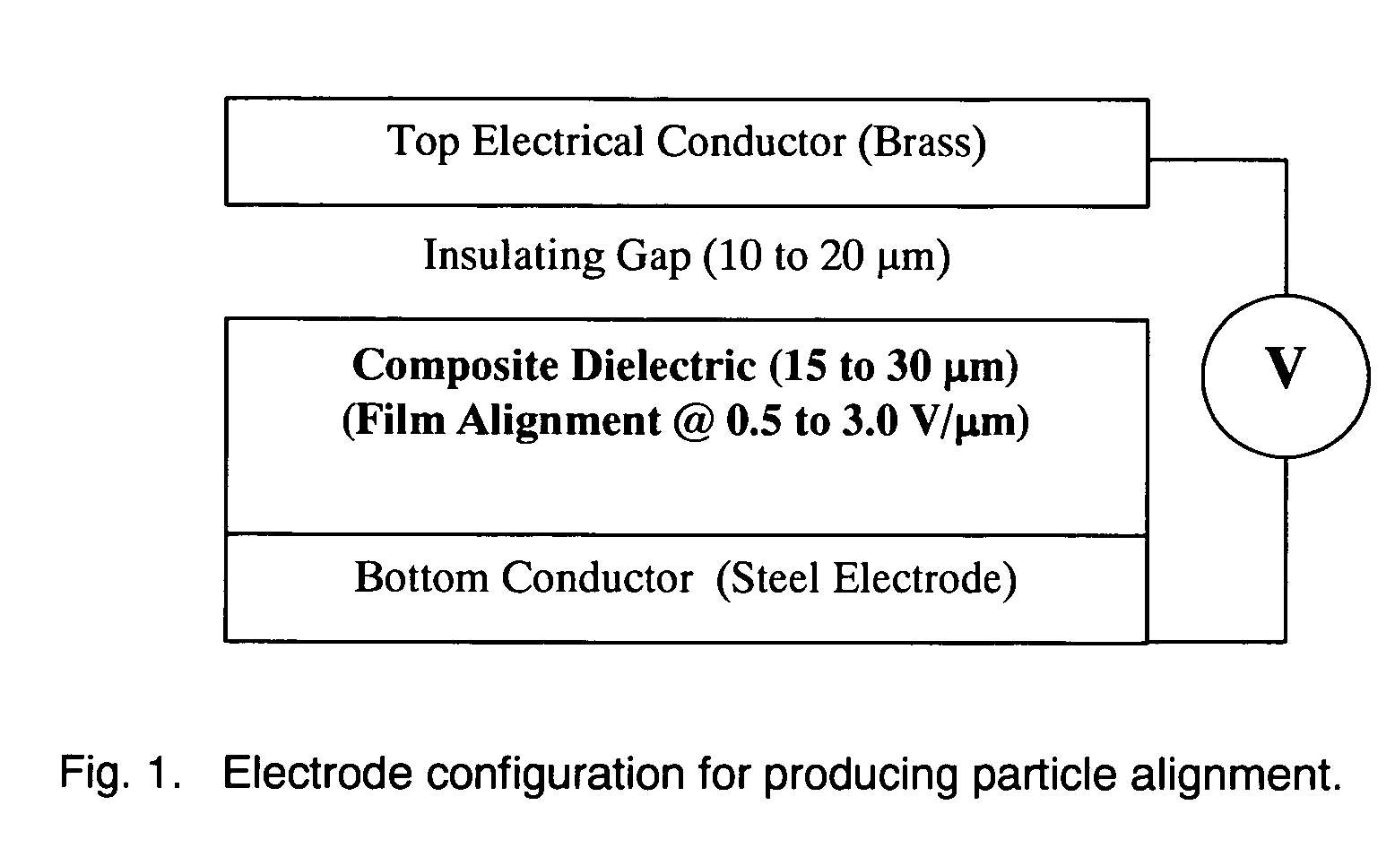
[0053] Barium titanate / epoxy slurries were evaluated using optical microscopy to identify alignment characteristics in the electric field. The dilute slurries were poured onto glass slides prepared with electrodes. The electrodes were made by wrapping insulated magnet wire around the glass slide and gluing the ends in place. The separation distance between the magnet wire was made as small as possible, approximately 1 mm. The insulation was stripped from the ends of the wire to allow electrical contact. A Variac and a step-up transformer were used to apply an electric field across the electrodes. The Variac and the transformer allowed for up to 400 V at a fixed frequency of 60 Hz. Because the separation distance was typically 1 mm, a field stress up to 4.0 V / μm field was applied.

[0054] A power amplifier was used in combination with an AC signal generator to provide the sinusoidal, low voltage signal for amplification at frequencies up to 40 kHz...


PUM

PropertyMeasurementUnit
energy densityaaaaaaaaaa
sizeaaaaaaaaaa

Abstract

The present invention provides a structured, nano-composite, dielectric film. The invention also provides a method for producing the thin composite film. The composite material comprises ceramic dielectric particles, preferably nano-sized particles, and a thermoset polymer system. The composite material exhibits a high energy density.

Description

CROSS-REFERENCE TO RELATED APPLICATIONS [0001] This application is a continuation-in-part application of U.S. patent application Ser. No. 11 / 019,810, entitled “Moldable High Dielectric Constant Nano-Composites”, filed Dec. 20, 2004, which claims priority to U.S. Provisional Patent Application Ser. No. 60 / 531,432, entitled “Moldable High Dielectric Constant Nano-Composites”, filed Dec. 19, 2003, and the specification and claims of those applications are incorporated herein by reference. This application also claims the benefit of the filing of U.S. Provisional Patent Application Ser. No. 60 / 576,383, entitled “Structured Composite Dielectrics”, filed Jun. 1, 2004, and the specification of that application is incorporated herein by reference. This application also is related to U.S. Pat. No. 6,608,760, entitled “Dielectric Material Including Particulate Filler” and U.S. Pat. No. 6,616,794, entitled “Integral Capacitance for Printed Circuit Board Using Dielectric Nanopowders”, and the s...

Claims


Application Information

Patent Timeline
Patent Type & Authority Applications(United States)
IPC IPC(8): C08K3/22
CPCC08K3/34H01G4/206H01L28/40H05K1/162H05K2201/0209H05K2201/0257H05K2201/0269H05K2203/105
Inventor SLENES, KIRK M.PERRY, DALELABANOWSKI, CHRISTOPHERPERRY, HOPELUTHER, ERIK
Owner TPL SRL
Why Eureka
Try Eureka